Once you have determined what electrical devices you will
be
powering with the generator,
connect these devices according to the following procedure:
1.
Plug
in
each electrical device with the device turned off.
a.
NOTE:
Be
sure to attach appliances to the correct receptacle (outlet). Connect
standard 120 Volt, single phase,
60
Hz loads only to the 120 Volt receptacle.
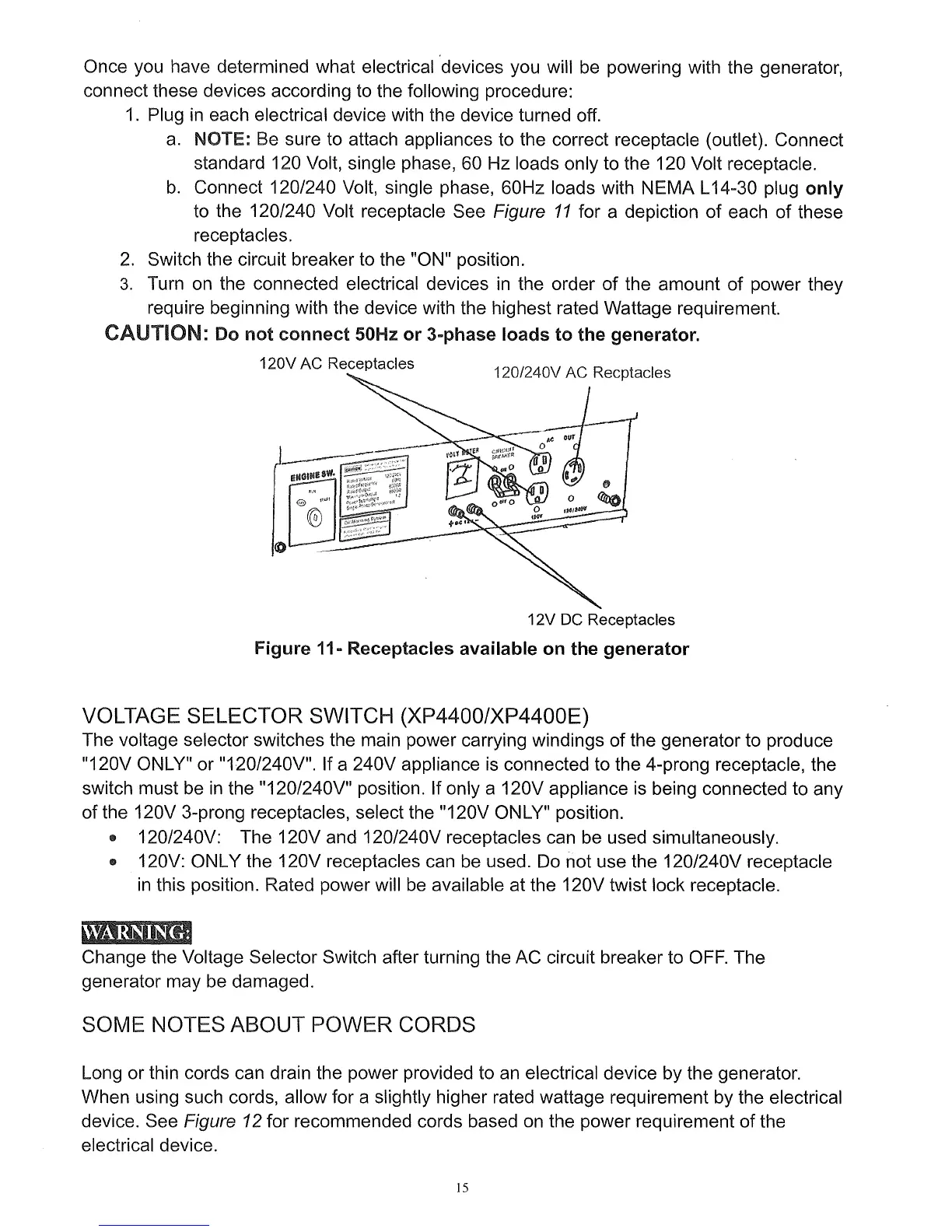
b.
Connect 120/240 Volt, single phase, 60Hz loads with NEMA L14-30 plug
only
to the 120/240 Volt receptacle See Figure
11
for a depiction of each of these
receptacles.
2.
Switch the circuit breaker to the "ON" position.
3.
Turn
on
the connected electrical devices
in
the order of the amount of power they
require beginning with the device with the highest rated Wattage requirement.
CAUTION: Do
not
connect
50Hz
or
3-phase loads
to
the generator.
120V AC Receptacles
12V DC Receptacles
Figure 11- Receptacles available
on
the
generator
VOLTAGE SELECTOR SWITCH (XP4400/XP4400E)
The voltage selector switches the main power carrying windings of the generator to produce
"120V ONLY" or
"120/240V". If a 240V appliance is connected to the 4-prong receptacle, the
switch must be
in
the "120/240V" position. If only a 120V appliance
is
being connected to any
of the 120V 3-prong receptacles, select the "120V
ON
LY" position.
• 120/240V: The 120V and 120/240V receptacles can be used simultaneously.
• 120V: ONLY the 120V receptacles can be used.
Do
not use the 120/240V receptacle
in
this position. Rated power will
be
available at the 120V twist lock receptacle.
Change the Voltage Selector Switch after turning the AC circuit breaker to
OFF.
The
generator may
be
damaged.
SOME NOTES ABOUT POWER CORDS
Long or thin cords can drain the power provided to
an
electrical device by the generator.
When using such cords, allow for a slightly higher rated wattage requirement by the electrical
device. See
Figure 12 for recommended cords based
on
the power requirement of the
electrical device.
15