42
Installation Manual
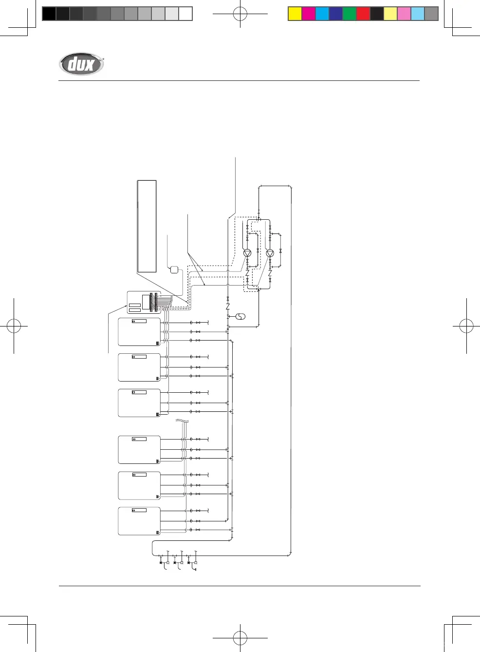
Unit 12 Unit 2Unit 3Unit 10Unit 11 Unit 1
Cold water supply pipe
(1 1/4” - 5”)
Hot Water Return Line (3/4” - 1 1/4”)
Hot Water Supply Pipe (1 1/4” - 5”)
(Size for max. flow)
Expansion
Tank
Hot water
supply points
....
When installing 2 pumps in parallel
Circulation pump 1
Circulation pump 2
Remote Controller
Pump Control Wires
(use external relays)
Set “Yes” for the question
“Start pump rotation?” in system settings.
(See SCU-401-12M Installation Manual)
*
Size the cold water supply piping to
allow for maximum flow rates
of the units.
B-1. Example of Recirculation with a Multi-System (Using external system controller)
This system will make hot water more quickly available to remote fixtures.
The pump will circulate water through the loop until the entire loop is warm, and then the system
controller will turn off the pump until the loop cools down.
* Size the pump to provide at least 8 L/min @ 3 m of head + piping losses through the system. Check
the maintenance monitors on the unit to make sure the pump is providing adequate flow.
•
Make sure that the flow rate is not greater than 1.2 m/sec.
(3/4”: 20 L/min, 1 1/4”: 50 L/min)
If the flow is too low, the recirculation loop temperature will not be warm enough, if the flow is too
high, the lifetime of the unit will be reduced.
* If there are multiple circulation loops, try to make the flow rate .3-5 L/min in each loop.
* Use copper or stainless water piping for the entire system.
(Recirculation system)
43
Installation Manual
Storage Tank Circulation pump 2
Storage Tank Circulation pump 1
Relief valve
Hot water
supply point
Hot water supply line
Hot water return line
Cold water supply pipe *1
When installing 2 pumps in parallel
Set “Yes” for the question
“Start pump rotation?” in system settings.
(See SCU-401-12M Installation Manual)
* Size the cold water supply piping to allow for
maximum flow rates of the building.
* Be sure to connect the cold water supply pipe
between the hot water storage tank and intake
side of the storage tank circulation pump.
Thermostat
Remote
controller
cord
Remote Controller
Pump control
(use external relays)
Unit 1Unit 2Unit 3Unit 10Unit 11Unit 12
(copper or stainless steel pipe)
Hot water
storage tank
(copper or stainless steel pipe)
Return line
circulation pump
(Size for max. flow)
(Size for max. flow)
Storage tank supply line
(copper or stainless steel pipe)
Storage tank return line
(copper or stainless steel pipe)
B-2. Example of Installation with a Storage Tank and Recirculation System (Using external system controller)
The pump will push water through the Multi-System to heat up the tank.
When the temperature of the thermostat is high, the system controller will turn off the pump until the
temperature cools down.
* For the set temperature of the remote controller, use the temperature (of the thermostat) + about 5 °C.
* To achieve the highest recovery, size the storage tank circulation pump for maximum capacity.
(34 L/min (each) @ 12 m of head (75 °C setting or less) + piping losses through the system.)
Verify the supply pressure to the units is at least 200 Kpa.
(Tank recirculation system)
SBB80RX_P001-P044_E_tonb.indd 42 2017/01/27 8:14:02