16
Installation Manual
• Maintain the same flue pipe diameter from the
heater flue to the flue terminal. The exhaust and
intake pipes must be the same flue pipe diameter.
Be sure to do
CARBON MONOXIDE POISONING
Follow all flue system requirements in accordance with relevant local or state regulation,
or, in the absence of local or state code.
• Make sure the flue system is gas tight and will
not leak.
• Support the flue pipe with hangers at regular
intervals as specified by these instructions or
the instructions of the flue manufacturer.
•
Do not store hazardous or flammable substances
near the flue termination and check that the
termination is not blocked in any way.
• Steam or condensed water may come out
from the flue termination. Select the location
for the termination so as to prevent injury or
property damage.
• If snow is expected to accumulate, take care
the end of the pipe is not covered with snow
or hit by falling lumps of snow.
General Requirements
WARNING
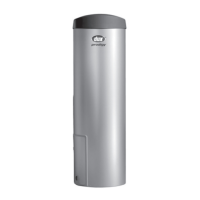
Flue Piping
The seals supplied with the heater must be installed into the flue tubes before connecting the heater to any flueing.
Failure to fit the seals may void warranty and may lead to personal injury
17
Installation Manual
Maximum Flue Length Adjustment DIP switches
0
1
2
3
4
5
6
7
8
9
10
11
12
13
14
m1023
Short length
Long length
Do not change any other DIP switches.
Flue length condition.
1
7
ON= OFF=
2
* Not including the flue terminal.
1
2
Long length
Short length
<Maximum Flue Length Configurations>
The unit can be adjusted to accommodate longer flue runs; refer to the below table to find the
maximum flue length based on the number of elbows. Adjust the DIP switches according to the flue
condition noted in the tables below.
Note:
By default, the unit has been set to the " 1 short length" condition.
- Two 90° elbows, maximum length = 1 m
(with DIP switches set at " 1 short length" condition)
- Two 90° elbows, maximum length = 11 m
(with DIP switches set at " 4 long length" condition)
[Maximum flue Length Example]
• Disconnect power to the water heater before changing the DIP switches. Failure to perform
this
step will result in a "73" code displayed on the remote controller and a cease in operation
. If this
occurs, disconnect, then reconnect power to the water heater to reset the system.
Note : Please refer to page 25 for the location of the DIP switch bank.
The power must be unplugged when adjusting
the DIP switches to switch the airflow amount.
SBB80RX_P001-P044_E_tonb.indd 16 2017/01/27 8:13:54