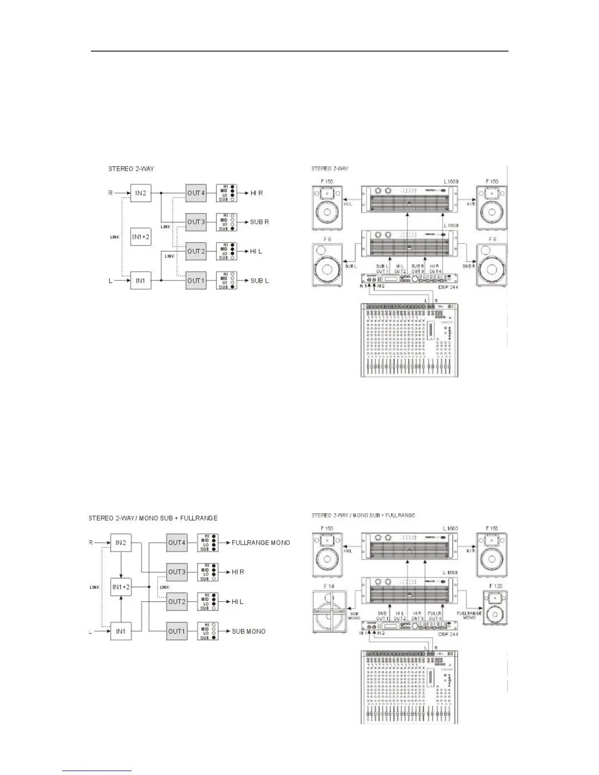
6.1 Stereo 2 Way
This configuration generally represents a 2-way stereo frequency crossover, where IN 1 serves as the
left input channel and IN 2 as the right input channel. OUT 1 is the left Low-range output and OUT 2 is
the left High-range output. OUT 3 and OUT 4 are the corresponding right Low-range and High-range
output channels. The parameters of the inputs 1 and 2 as well as the ones of the Low-range and High-range
outputs are always set to identical values; i. e.: the left and right channels are linked. The following figures
illustrate the input / output routing of a typical STEREO 2-WAY installation.
6.2 Stereo 2 Way / Mono Sub + Fullrange
This configuration represents a 2-way frequency crossover with monaural sub-channel and additional
Fullrange output. OUT 1 is the sub-channel that is fed by the summed audio signals of the inputs IN 1
and IN 2. OUT 2 and OUT 3 are the left and right High-range output channels. OUT 4 is a Fullrange output
that is also fed by the summed signal of the inputs IN 1 and IN 2. For example, this output signal can be
used to provide sound reinforcement in adjacent rooms. The parameters of the inputs 1 and 2 as well as
the ones of the two High-range outputs are always set to identical values; i. e.: the left and right channels
are linked. The following signal flow diagram is meant to illustrate the input / output routing scheme. The
figure on the right bottom shows a typical configuration with monaural sub woofer and additional Fullrange
installation.
CONFIGURATIONS OF THE DSP 244
6-2