Do you have a question about the Dynacord L500 and is the answer not in the manual?
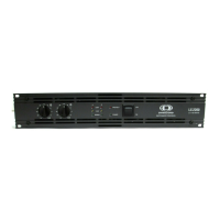
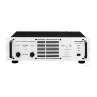
Adjusts the total gain of the power amplifier, with calibrated detented potentiometers.
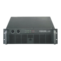
LED indicating the unit is connected to mains and the mains switch is pressed.
LED indicating a signal is present at the power amplifier input.
LED indicating a signal is present at the power amplifier output.
Indicates when the limiter is activated, signaling clip level operation.
Lights up when protection circuits (over-temp, overload, etc.) are triggered.
Main switch for powering the unit on, with delayed output activation.
XLR connectors for signal input, wired parallel to other amplifiers for looping.
Defines pin assignments (SHIELD, hot, cold) for XLR input connectors.
Input channels A and B wired in parallel; volume controlled independently.
Input channels A and B amplified separately.
SPEAKON connectors for output channels A and B, and Bridged Out.
Adjusts limiter time constant for different frequency amplifier use.
Selects between Normal Stereo and Mono Bridged operation modes.
Attenuates subsonic and high frequency signals to prevent modulation.
Separates chassis from circuit ground to help prevent hum loops.