DEVICE DESCRIPTIONS
5-88 PROMATRIX System User Handbook 1.2
5.6.3 DCS 422R LF-INPUT SWITCHING
In case of power amp failure, the DCS 422R module switches the LF-signal over to the assigned spare amplifier.
The DCS 422R module provides four balanced input channels (parallel connection via internal jumpers is
possible) and five LF-output channels. Each input offers electronic switching to the corresponding spare channel.
The internally generated pilot tone signal (the generated signal can be switched via software) is summed on the
five electronically balanced output stages. The four FAULT-LEDs
F1
to
F4
(red) indicate channel failure. The
PILOTTON-LED
PT
(green) indicates the pilot tone generator’s state of operational readiness. The
CC
In/Out-
connector allows cascading the LF-signal for the spare amplifier via several DCS422R modules.
•
Pluggable terminal clamps with screw-in flange for all inputs and outputs, 30 contacts
•
4 LF-inputs, electronically balanced
•
4 electronic switches for switching the LF-signal to the spare amplifier
•
5 internal channel-amps with pilot tone summing
•
5 LF-outputs, electronically balanced, 600 ohms
•
Pilot tone generator, switchable via software
•
4 LEDs for “FAULT”-messaging (red), 1 LED for pilot tone ON/OFF (green)
•
Internal jumpers for parallel connection of LF-inputs 1 to 4
•
1 IN/OUTPUT for cascading the LF-signal via several DCS 422R modules
Installation Note
The module has to be installed in the DCS 400 base unit in slots 2-10 (counted from left to right).
Caution!
Slot 1 (the slot all the way on the left hand side) has to be equipped with a DCS 421R control module
respectively with a DCS 405R extension module.
The next slots have to be equipped with DCS 422R / DCS 423R modules always in ascending order (from left to
right) and without empty slots in-between.
When installing the module and establishing connections make sure to comply with VDE 0100 and EN 60065
regulations.
Specifications:
Operating Voltage 24 V DC, -10 / +30%
Operating Current 93 mA ... 99 mA
Operating Temperature Range +5° C ... +40°C
Dimensions (W x H x D) 37.5 x 80.6 x 245 mm
Weight 212 g
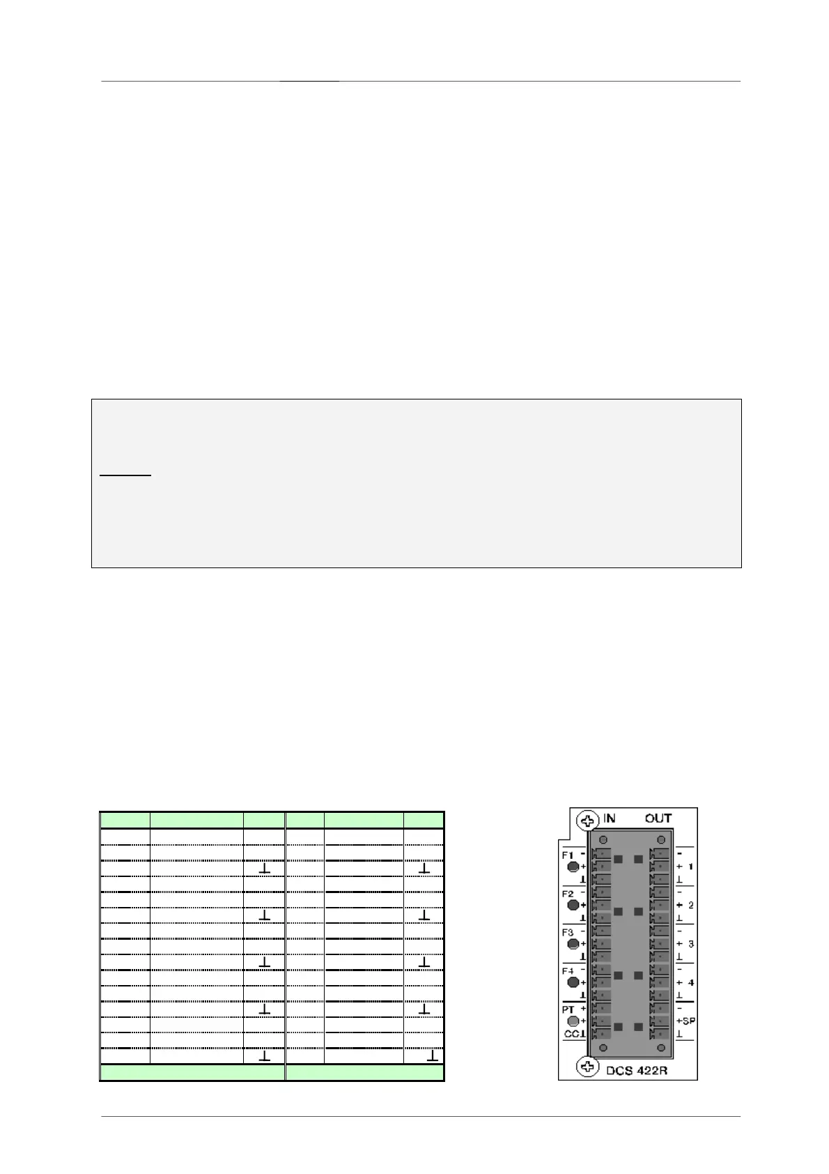
Connector Pin-Assignment DCS 422R
PIN Connector A BEZ
PIN Connector B
BEZ
1 OUT 1 - - 16 INP 1 - -
2 OUT 1 + + 17 INP 1 + +
3 GND 1 18 GND 1
4 OUT 2 - - 19 INP 2 - -
5 OUT 2 + + 20 INP 2 + +
6 GND 2 21 GND 2
7 OUT 3 - - 22 INP 3 - -
8 OUT 3 + + 23 INP 3 + +
9 GND 3 24 GND 3
10 OUT 4 - - 25 INP 4 - -
11 OUT 4 + + 26 INP 4 + +
12 GND 4 27 GND 4
13 OUT SPARE
- 28 IN/OUT CC
+
14 OUT SPARE
+ 29 IN/OUT CC
+
15 GND SPARE 30 GND CC CC
OUT IN
 Loading...