DEVICE DESCRIPTIONS
PROMATRIX System User Handbook 1.2
5-9
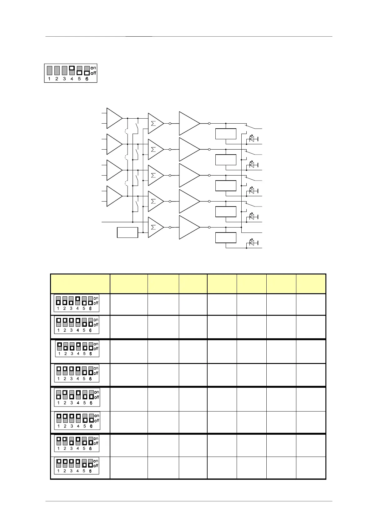
Multi-Channel Configuration
This configuration is used for spare device switching in multi-program installations.
Input and output signals of the affected power amplifier are switched over to the
corresponding spare amp in case of power amp failure.
An equal amount of DCS 422R and DCS 423R modules is employed (a minimum of one of each). The pilot tone
signal is generated in the DCS 422R module(s) (generator active).
The following table shows a listing of needed modules for the design of different spare systems in multi-channel
configuration.
DCS 421R
SETUP
SPARE
AMPs
AMPs
DCS
400
DCS
405R
DCS
421R
DCS
422R
DCS
423R
1 1-4 1 0 1 1 1
1 Max. 32
2 2 1 8 8
2 2-8 1 0 1 2 2
2 Max. 32
2 2 1 8 8
3 3-12 1 0 1 3 3
3 Max. 24
2 2 1 6 6
4 4-16 1 0 1 4 4
4 Max. 16
1 0 1 4 4
 Loading...