DEVICE DESCRIPTIONS
PROMATRIX System User Handbook 1.2
5-8
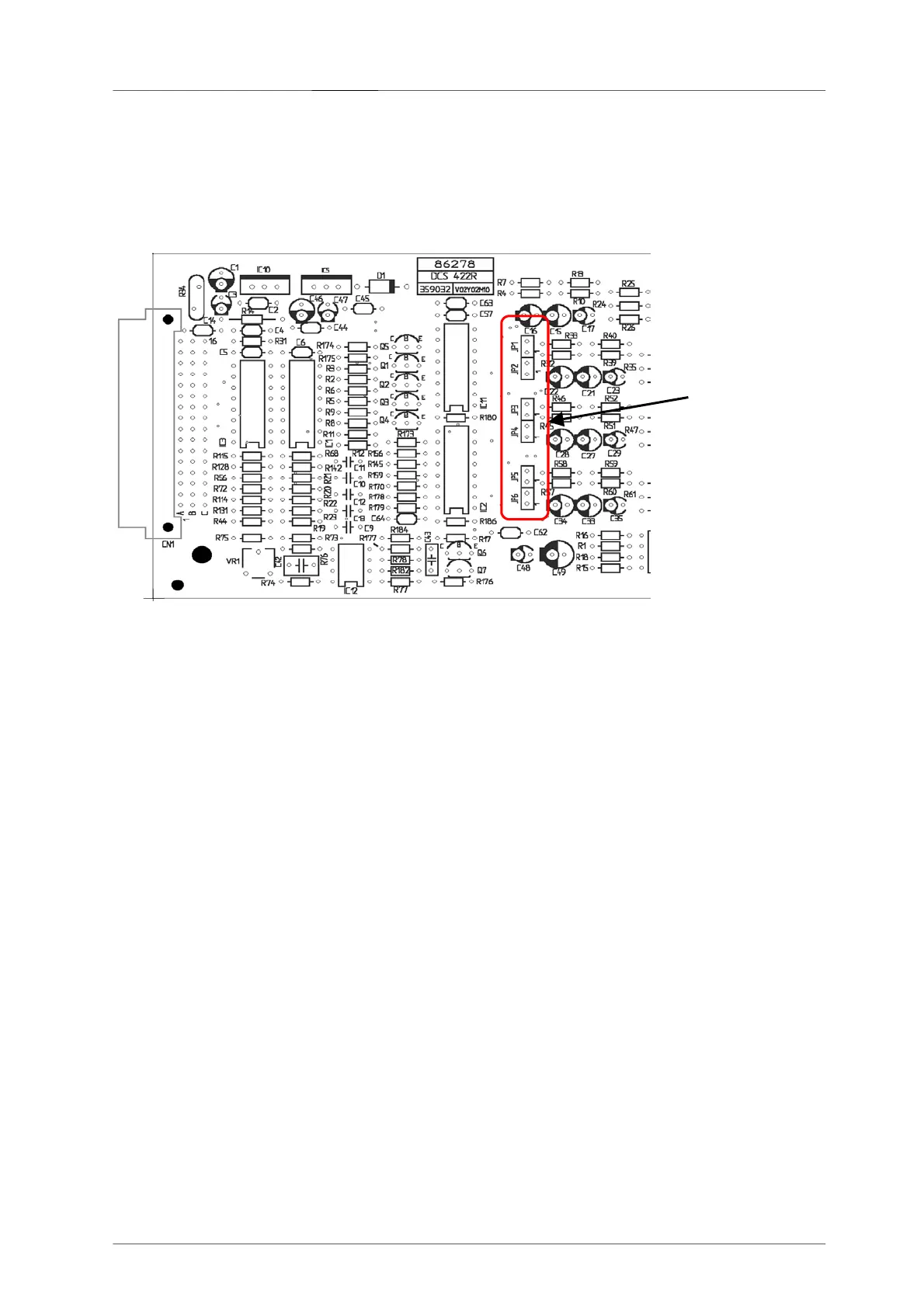
LF-Inputs
The LF-inputs IN1 – IN4 with a sensitivity of 775 mV (0 dBu) are electronically balanced. The jumpers JP1 ... JP6
[1]
on the PCB 86278 allow for parallel connection of the inputs, so that several different power amplifiers can
transmit the program of a single source (see also block diagram DCS 422R).
LF-Outputs
The LF-outputs OUT1 – OUT4 and OUT SPARE
with a nominal output voltage of 775 mV (0 dBu) into a load of
600 ohms are electronically balanced.
Control Indicators
F1 ... F4: FAULT-LEDs (red) – light whenever the corresponding monitored power amp ceases operation
PT: Indication-LED (green) – lights whenever the internal pilot tone generator has been activated
IN/OUT Cascading (CC)
Allows cascading the LF-signal for the spare amp via several DCS 422R modules. The INPUT / OUTPUT with a
sensitivity of 590 mV into 600 ohms is unbalanced.
Block Diagram
A block diagram of the modules DCS 422R and DCS 423R can be found on page 5-93.
 Loading...