DEVICE DESCRIPTIONS
5-68 PROMATRIX System User Handbook 1.1
5.5 DCS 400R
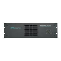
5.5.1 DCS 400 19″ CENTER UNIT
The DCS 400 19” base unit with a height of 2 HU can host controller, relay, logic input, and analog I/O modules
that are connected via internal backplane.
• 10 slots for the insertion of DCS 4XXR modules.
• 4-pole plug-binding post for power supply, +24V and negative pole.
• 2 LED’s on the front indicating power presence and active.
• Internal backplane with system bus.
• Internal self-resetting fuses for the positive and negative poles.
Installation Notes
When equipping the DCS 400 center unit make sure to mind the following:
• Always insert a DCS401R control module in slot 1(the slot all the way on the left).
• Always equip the slots 1-10 in ascending order (from the left to the right) leaving no empty slots
in-between.
Mounting the unit and establishing the connections is solely admissible when performed in accordance
to VDE 0100 and EN 60065 regulations.
Specifications:
Operating voltage 24 V DC, -10 / +30%
Operating temperature range +5° C ... +40°C
Dimensions (W x H x D) 19”, 2HE
483 x 88,1 x 336,5mm
Weight 5,6 kg