DEVICE DESCRIPTIONS
PROMATRIX System User Handbook 1.1
5-18
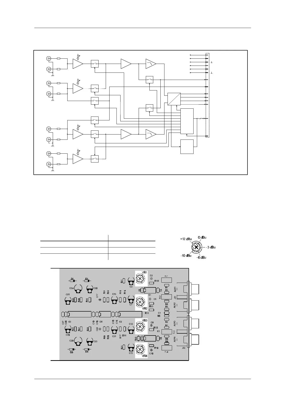
Block Diagram:
MCLK
BCLK
WCLK
DIN
ANALOG
SUPPLY
DIGITAL
SUPPLY
BOARD
STATUS
& ID
SPI
INTERNAL MONITOR
+12V
-12V
+5V
+24V
BOARD
CONTROL
4
2 CHANNEL
DIGITAL
AUDIO
RES
A
D
IN A
PILOT
L
AUX 1
R
L
AUX 2
R
AUX 1
AUX 2
PILOT B
PILOT A
MON B
MON A
AUX 2
GAIN
AUX 1
GAIN
IN B
L
AUX 3
R
L
AUX 4
R
AUX 3
AUX 4
AUX 4
GAIN
AUX 3
GAIN
figure 5.20 block diagram 2-channel AUX input module
Internal Settings:
AUX input sensitivity setting
Using trimmers VR1 (AUX 1), VR2 (AUX 2), VR3 (AUX 3) and VR4 (AUX 4), adjusting input levels is possible
in a range between -10 dBu and +12 dBu. The trim-potentiometers' coarse scales are meant for your
convenience, helping you in adjusting the levels.
Potentiometer setting Input level
Left margin +12 dBu
Center position -3 dBu
right margin -10 dBu
figure 5.21 internal settings, location of parts (NRS 90228)