DEVICE DESCRIPTIONS
5-90 PROMATRIX System User Handbook 1.2
5.6.4 DCS 423R 100V RELAY SWITCHING
The DCS 423R provides 5 channels for pilot tone signal examination. The sensitivity can be set via jumpers. The
100V-signal (70V/50V) of up to 4 power amps gets monitored and in case of failure the signal is switched over to
the corresponding spare amp. Disabling the fault-message for channels that are not in use is possible by
removing the corresponding jumper. The corresponding FAULT-LEDs
F1
–
F4
(red) lights on the occurrence of a
channel failure. The LED
FSP
(FAULT SPARE, red) lights when one of the spare amps fails to operate.
•
Pluggable terminal clamps with screw-in flange for all inputs and outputs, 30 contacts
•
4 relays with 2 switching contacts each for the 100V-outputs (70V/50V-outputs)
•
5 integrated pilot tone examination circuits with selectable sensitivity via internal jumper setting
•
5 FAULT-LEDs for fault-messaging
•
Message outputs for AMP1 to AMP 4 and AMP SPARE with a power rating of 200 mA each
•
1 IN/OUTPUT for cascading the 100V–signal (70V/50V) via several DCS 423R modules
•
The output lines of the amplifier outputs have to be twisted and shielded to provide improved noise immunity
Installation Note
The module has to be installed in the DCS 400 base unit in slots 2-10 (counted from left to right).
Caution!
Slot 1 (the slot all the way on the left hand side) has to be equipped with a DCS 421R control module
respectively with a DCS 405R extension module.
The next slots have to be equipped with DCS 422R / DCS 423R modules always in ascending order (from left to
right) and without empty slots in-between.
When installing the module and establishing connections make sure to comply with VDE 0100 and EN 60065
regulations.
Specifications:
Operating Voltage 24 V DC, -10 / +30%
Operating Current 39 mA ... 63 mA
Input Voltage 150 mV / 500 mV at 19kHz
Relay Switching Contacts 2 changers, 2SPDT, AgNi 90/10, 2000 VA, 100 V AC / 8A
Operating Temperature Range +5° C ... +40°C
Dimensions (W x H x D) 37.5 x 80.6 x 245 mm
Weight 375 g
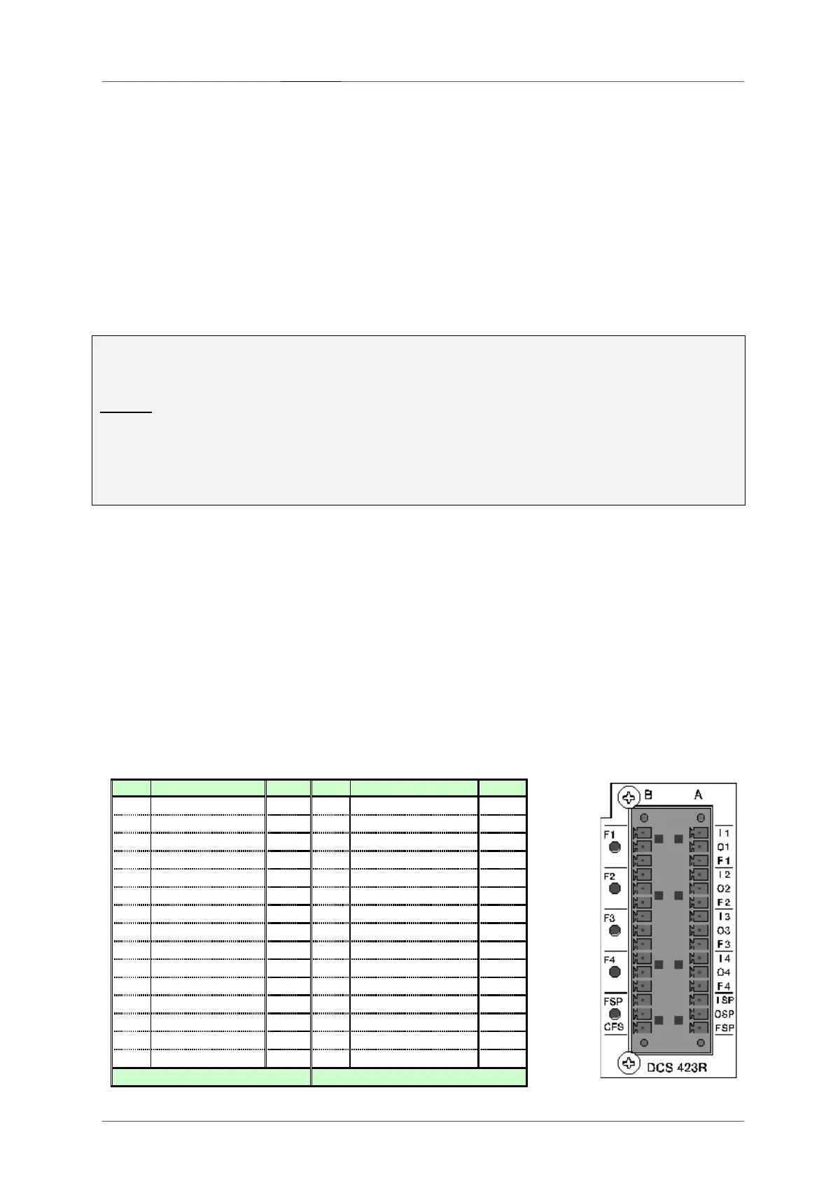
Connector Pin-Assignment DCS 423R
100V-Inputs
PIN
Connector A BEZ PIN Connector B BEZ
1 INP 1+ I 1 16
INP 1-
2 OUT 1+ O1 17
OUT 1-
3 Fault Amp 1 F1 18
N.C.
4 INP 2+ I 2 19
INP 2-
5 OUT 2+ O2 20
OUT 2-
6 Fault Amp 2 F2 21
N.C.
7 INP 3+ I3 22
INP 3-
8 OUT 3+ O3 23
OUT 3-
9 Fault Amp 3 F3 24
N.C.
10
INP 4+ I4 25
INP 4-
11
OUT 4+ O4 26
OUT 4-
12
Fault Amp 4 F4 27
N.C.
13
Input Spare + ISP
28
Input Spare -
14
Output Spare + OSP
29
Output Spare -
15
Fault AMP Spare
FSP
30
Collecting Fault Signal CFS
-A- -B-
 Loading...