DEVICE DESCRIPTIONS
PROMATRIX System User Handbook 1.2
5-9
The inputs
I1
-
I4
and
ISP
(Spare) are balanced and floating. The 100V-signal is connected through via relay from
IN to OUT. The 100V-signal is switched over to the spare amp channels
ISP
in case of failure of a power
amplifier.
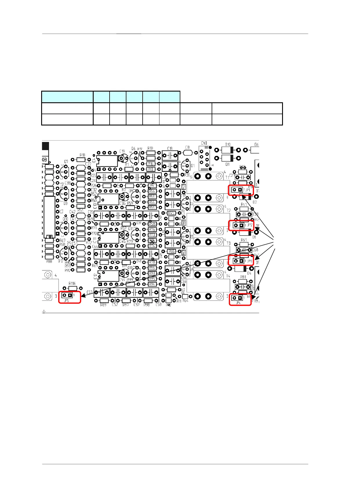
The pilot tone signal is decoupled via transformer and evaluated via DETECT-circuit. Setting the sensitivity is
possible on the PCB 86279 using the jumpers JP1 ... JP5 [2].
Sensitivity JP1
JP2
JP3
JP4
JP5
High (ca. 150 mV) 0 0 0 0 0 0 = open Factory default setting
Low (ca. 500 mV) 1 1 1 1 1 1 = closed
Control Indicators
F1 ... F4: FAULT-LEDs (red) – light whenever the corresponding monitored power amp ceases operation
FSP: FAULT-LED (red) – lights whenever the spare amp fails to operate
Fault-Message Outputs (FAULT AMP)
F1 – F4 / FSP: Control (switched) outputs and control indicators F1 - F4 and FSP are in their functioning
identical. They can be operated with a max. power rating of 200 mA against +24V.
CFS: COLLECTING FAULT SIGNAL is a collective fault-message, i.e. the CFS-output is active
when one of the four monitored power amps fails to operate. The output can be operated
with a max. power rating of 200 mA against +24V.
 Loading...