DEVICE DESCRIPTIONS
PROMATRIX System User Handbook 1.1 5-21
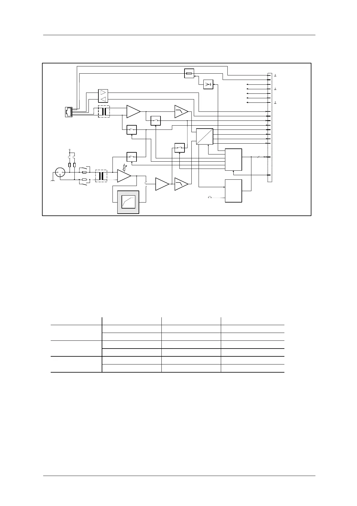
Block Diagram:
MCLK
BCLK
WCLK
DIN
ANALOG
SUPPLY
DIGITAL
SUPPLY
BOARD
STATUS
& ID
SPI
INTERNAL MONITOR
+12V
-12V
+5V
+U24
BOARD
CONTROL
4
2 CHANNEL
DIGITAL
AUDIO
RES
A
D
AUDIO
RS-485
NRS 90208
ELECTRONIC
PROGRAMMABLE
FUSE
24V
DPC 4000
IN A
PILOT
RX485
TX485
PILOT A
MON A
MON B
NRS 90233
IN B
1 2
3
+24V
MIC
LINE
COMPRESSOR /
LIMITER
MIC/
LINE
PILOT B
GAIN
JP2
LIN
COMP
JP1
1
2
3
4
LINE
MIC
JP1
5 6
figure 5.25 block diagram MIC/LINE + paging station module
Internal Settings:
1. MIC / LINE switching and sensitivity of the MIC / LINE input
The MIC / LINE input's internal PAD-switch (S1) allows switching the channels' sensitivity between
microphone and line levels (30 dB). The GAIN-control on the module's front panel is provided to precisely
adjust the input sensitivity (range 40 dB).
In addition, a MIC/LINE jumper (JP1, pins 5-6) is located on the printed board assembly, which allows
correctly configuring the input. It is important to change the jumper accordingly (open = LINE, closed = MIC)
when changing the MIC/LINE switch.
When shipped the switch S1 is pre-set to LINE and the jumper JP1 to its open position.
GAIN setting MIC / LINE setting MIC / LINE jumper Input level
Left margin MIC Closed -14 dBu
LINE Open +16 dBu
Center position MIC Closed -28 dBu
LINE Open +2 dBu
Right margin MIC Closed -54 dBu
LINE Open -24 dBu
2. Phantom power
Closing the pins 1-2 and 3-4 of the jumper JP1 offers the possibility to engage 24 V phantom power for
microphones that are connected directly. When shipped, the jumper is factory pre-set to its “open” position (no
phantom power).
3. Compressor / Limiter
The MIC / LINE input channel embodies a compressor / limiter circuit which can be incorporated into the
signal path via jumper JP2 (position COMP). Normally, the compressor / limiter should be used to eliminate
the risks of overdrive and clipping, when directly connecting a microphone. When shipped, the jumper is pre-
set to its “Linear” position (LIN).


 To Next Page