DEVICE DESCRIPTIONS
5-56 PROMATRIX System User Handbook 1.1
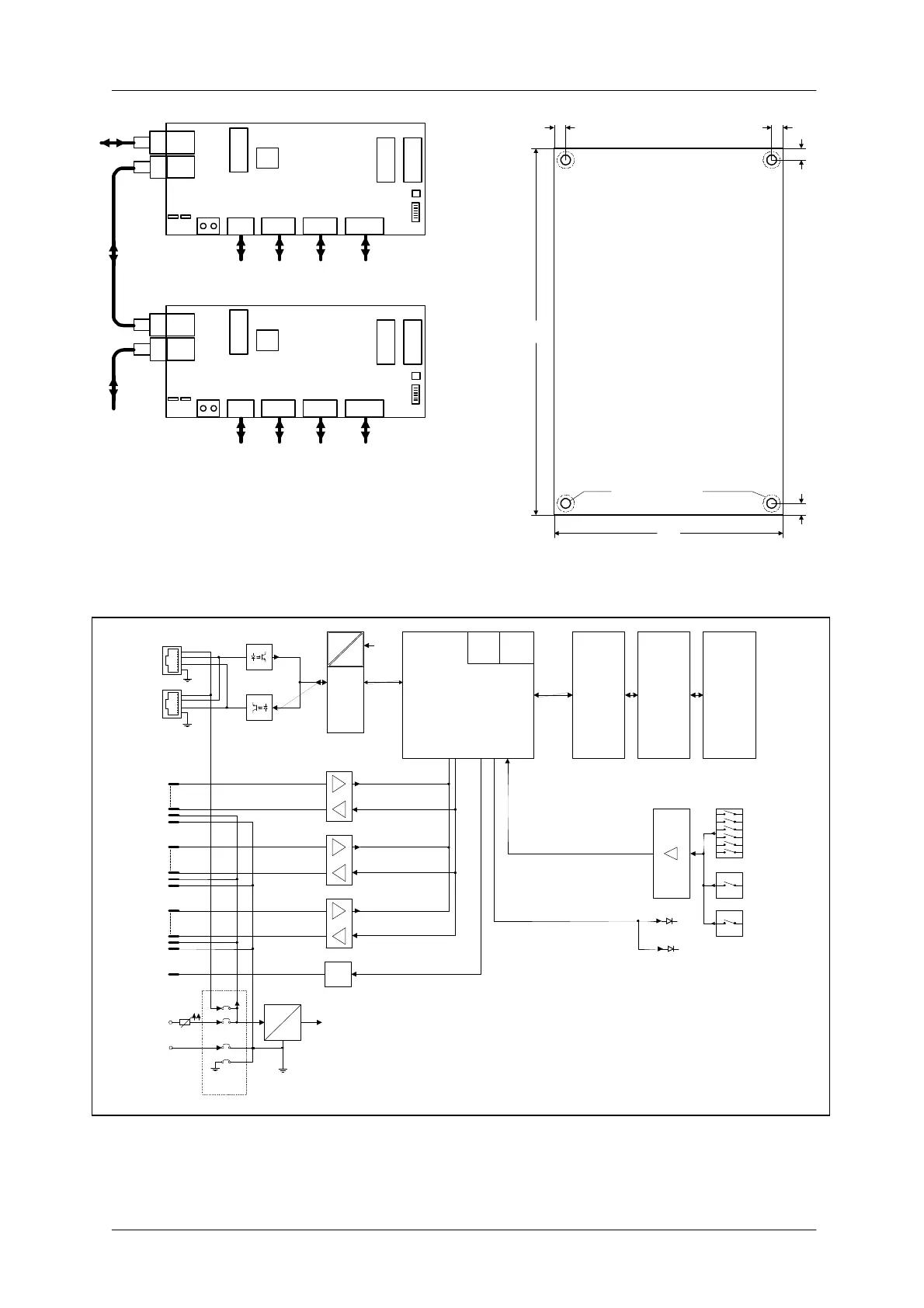
Maximally 8 DCS 401 modules can be cascaded.
Use jumpers CN3 and CN5 to select the supply
voltage source connector (CN1/CN2 or CN4).
S1 sets the address for each DCS 401.
The modules are initialized by pressing the
pushbutton S2
RS 485
DCS 401
CN2
CN1
CN4
24V-
CN3
CN5
CN7 CN8 CN9CN12
S1
DCS 401
CN2
CN1
CN4
24V-
CN3
CN5
CN7 CN8 CN9CN12
S1
2 Rotary
Encoder
DCS 408/9
Chain
DCS 412
Chain
DCS 416
Chain
S2
S2
5
5
100
160
∅
4,2
Mounting insulators
max
∅
7,5
5 5
Dimensions of the DCS 401 module
Size in mm
Module height 25 mm
The distance between the soldered
surface and an electrical conductive
mounting base has to be at least 5 mm
BLOCKDIAGRAM DCS 401
1
1
D
C
B
A
+5V
DC
DC
CPU
EPROM SRAM EEPROM
Watch
dog
RS485
Reset
DCS401-Address
S1
INIT
S2
Test
TP1
LED1
LED2
2 x Rotary
Encoder
CN12
DCS416
CN9
DPM4000
or DCS401
CN2
+5V
1
DC
DC
DPM4000
or DCS401
CN1
DCS412
CN8
DCS408/9
CN7
+24V
KL
CN4
-24V
KL
Jumper
CN3, CN5
t