Page 2
3101C Gen II MANUAL
11/17
INSTALLATION INSTRUCTIONS
705 Emmett Street Bristol, CT 06010
1-877-DynaLock www.dynalock.com
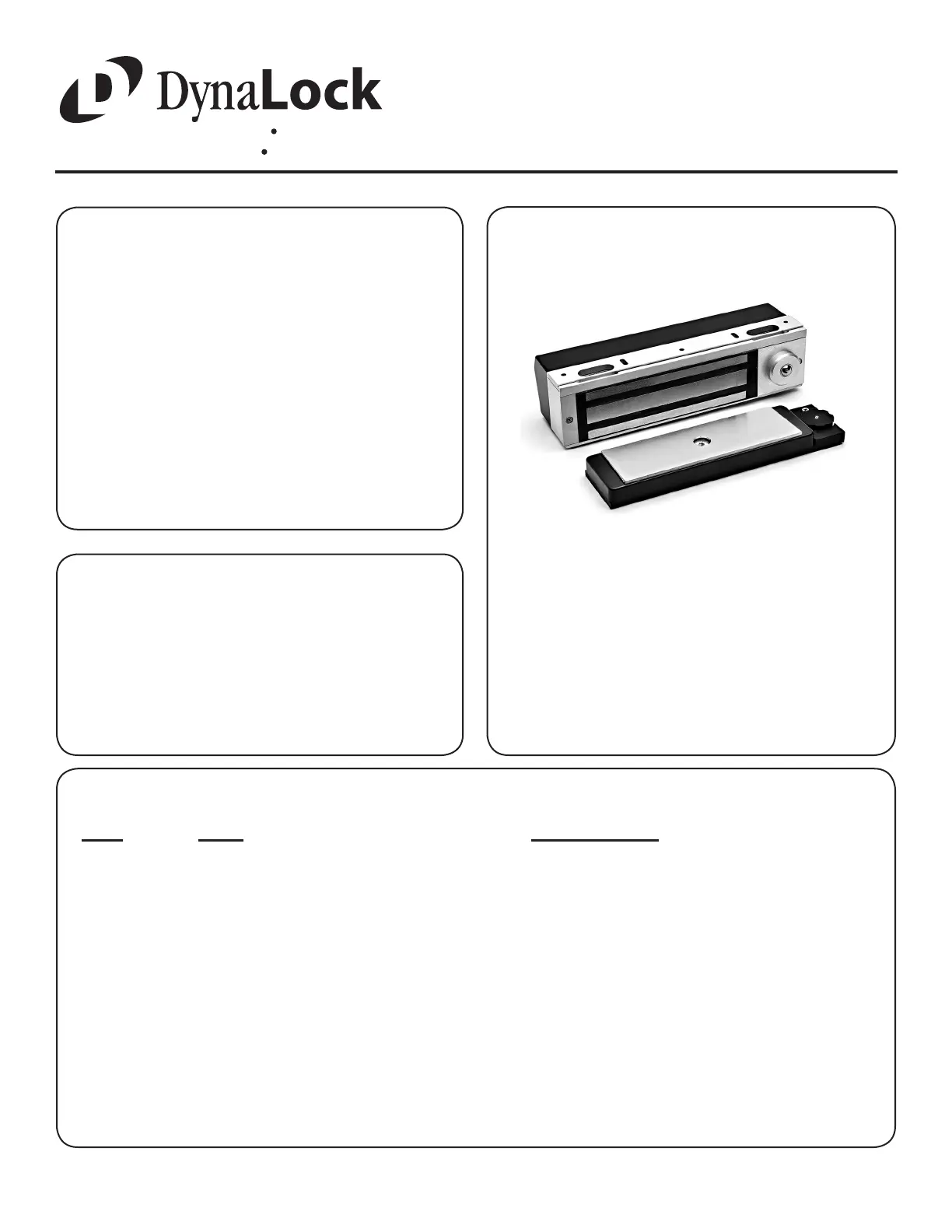
3101C
DELAYED
EGRESS LOCK
(GENERATION II)
MODEL #3101C BILL OF MATERIALS
(1) 3101C LOCK ASSEMBLY
(1) ARMATURE
(1) ARMATURE HOUSING
(1) ARMATURE MOUNTING PLATE ASSEMBLY
(1) HARDWARE KIT
(1) DOOR SIGN - “15 SECONDS” *
(1) TEMPLATE
(1) INSTALLATION MANUAL
(1) Electric Drill
(1) #2 Phillips Screwdriver
(1) Soft Faced Mallet
(1) Hammer
(1) Center Punch
(1) Pencil & Tape
Drill Bits: 1/8”, 5/16”, 3/8”, 9/16”
REQUIRED TOOLS
(5) Fas-Trak Mounting Screws #10 x 1” phillips pan head tek screw
(5) Fas-Trak Mounting Screws 10-24 x 1/2” phillips pan head machine screw
(1) Armature Mounting Screw 5/16-18 x 1” hex at head machine screw, turned
(1) Armature Spacer 3/8”D x 0.360”L
(1) Armature Spring Compression spring
(4) Armature Mounting Plate Screws #10 x 1” phillips at head sheet metal screw
(4) Armature Housing Mounting Screws 8-32 x 3/8” phillips machine screw
(1) Anti-Tamper Cover Screw Driver Bit T10 Pin Torx Driver Bit
(1) Fas-Trak Set Screw Wrench 1/8” ball head hex wrench
(1) Armature Bolt Wrench 3/16” hex wrench
(1) Thread Locking Compound Liquid
(2) Bypass/Reset Key
(1) Mini Screwdriver
NOTE: For further parts clarication refer to the Exploded Parts View on page 14 or consult factory.
HARDWARE KIT CONTENTS (PN 301556)
QTY.
ITEM
DESCRIPTION
General Information........................................... 1
Bill Of Materials................................................. 2
Using The Template........................................... 3
Mounting The Armature Assembly...................... 4
Mounting The Lock............................................. 5
Basic Set-Up...................................................... 6
Basic Wiring...................................................... 7
Egress Sensor Adjustment................................. 8
Indicator Descriptions......................................... 9
Optional Set-Up................................................. 10
Option Wiring..................................................... 11-12
Factory Wiring................................................... 13
Exploded Parts View.......................................... 14-15
TABLE OF CONTENTS
* “30 SECONDS” SIGN AVAILABLE