EasyManua.ls Logo

DynaLock 3101C - User Manual

DynaLock 3101C
16 pages
Print Icon
To Next Page IconTo Next Page
Loading...
Page 1
3101C Gen II MANUAL
11/17
INSTALLATION INSTRUCTIONS
705 Emmett Street Bristol, CT 06010
1-877-DynaLock www.dynalock.com
3101C
DELAYED
EGRESS LOCK
(GENERATION II)
The 3101C Delay Egress System is a 1500 pound
holding force (holding force not evaluated by UL)
electromagnetic lock electronically controlled to
provide a 15 or 30 second delay in unlocking.
The 3101C requires both mechanical and electrical
installation procedures as described herein.
When completed, a simple adjustment procedure to
set door movement will nalize the installation.
INSTALLATION DESCRIPTION
ELECTRICAL INSTALLATION
After mechanical installation is complete the 3101C needs to be wired and adjusted. A continuous power source, 12
or 24 VDC or VAC is required. Once low voltage power is supplied the unit is fully operational. Delay egress systems
also normally require re panel tie-in. All other wiring is for selected options.
NOTE: Please see Egress Sensor Adjustment (page 8) before applying power.
Familiarize yourself with the door and frame conditions. The lock must mount rigidly to the underside of the door
frame header and against the vertical strike jamb. The door mounted armature is supplied with hardware that allows
it to pivot slightly and pull away from the door as part of the delayed egress function.
NOTE: This lock does not change hands to match the hand of the door. Do not remove the coil assembly
from the lock housing.
NOTE: For locks ordered with the DSM option, please verify that two magnets are installed inside the
armature housing.
MECHANICAL INSTALLATION
The electromagnetic lock and armature are ruggedly constructed and designed to provide years of trouble-free
service. Care must be taken during installation and use, so that the lock face and armature face are kept free of dirt,
rust, paint, or any other obstruction which may interfere with the lock and armature making good contact.
HANDLING
Question and Answer IconNeed help?

Do you have a question about the DynaLock 3101C and is the answer not in the manual?

Summary

INSTALLATION OVERVIEW AND PREPARATION

Product Description

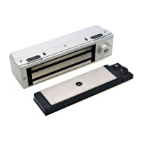
The 3101C Delay Egress System is an electromagnetic lock electronically controlled to provide a 15 or 30 second delay.

Handling Precautions

Care must be taken to keep lock and armature faces free of dirt, rust, paint, or obstructions.

Mechanical Installation

Mount lock rigidly to the underside of the door frame header and against the vertical strike jamb.

Electrical Installation

After mechanical installation, the unit needs wiring and adjustment with a continuous power source.

INSTALLATION COMPONENTS AND PROCEDURES

Required Tools

Lists necessary tools for installation, including drill bits and screwdrivers.

Hardware Kit Contents

Details the items included in the hardware kit, specifying quantity and description.

Mounting Considerations

Inspect door frame for angle bracket, spacer, or filler plate requirements for mounting.

Using the Template

Instructions on how to use the provided template to mark drilling locations for installation.

ASSEMBLY AND SETUP

Mounting the Armature Assembly

Attaching the armature mounting plate and armature to the door using specified screws and components.

Mounting the Lock Assembly

Steps for mounting the lock to the Fas-Trak baseplate and securing it to the header.

Basic Set-Up

Exposing the circuit board, understanding the LED array, and setting system selector switches.

WIRING AND CONFIGURATION

Basic Wiring

Details on power input terminals and fire panel input terminals for basic hook-up.

Egress Sensor Adjustment

Step-by-step guide to adjust the egress sensor for proper door latching and delay egress triggering.

Operation Modes

Describes keyswitch functions, indicator signals, and audible descriptions for various conditions.

Optional Set-Up

Configuration of system selector switches (S3) for various functions and modes.

ADVANCED OPTIONS AND WIRING

Option Wiring - Input Terminals

Details on remote reset, bypass, and trip input terminals for enhanced functionality.

Option Wiring - Output Terminals

Describes SPDT relay contacts for monitoring delay egress, Dynastat, DSM, ATS, and auxiliary alarm outputs.

Factory Wiring

Diagram illustrating factory wiring connections for the lock coil, sensors, and key switch.

PARTS AND SUPPORT

Exploded Parts View

Visual representation of all lock components with dimensional references.

Exploded Parts View Legend

Table listing each part number, description, and corresponding item number from the exploded view.

DynaLock 3101C Specifications

General IconGeneral
Power Supply12/24 VDC
MaterialMetal
FinishStainless Steel
Voltage12/24 VDC
Operation ModesFail-Secure
CompatibilityAccess control systems