Page 7
3101C Gen II MANUAL
11/17
INSTALLATION INSTRUCTIONS
705 Emmett Street Bristol, CT 06010
1-877-DynaLock www.dynalock.com
3101C
DELAYED
EGRESS LOCK
(GENERATION II)
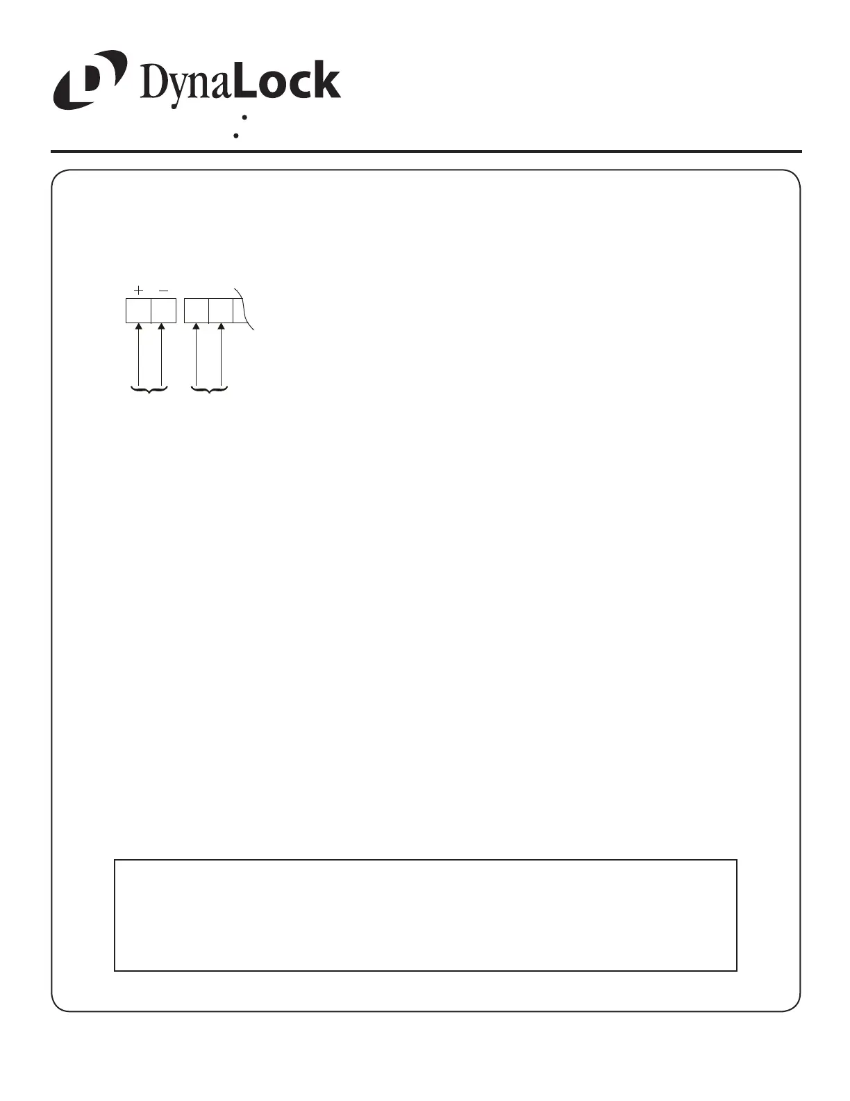
BASIC WIRING
Terminals 1& 2 - Auto-Sensing Power Input. May be 12 or 24 Volts, AC
or DC, uninterrupted. Maximum current draw, by voltage, is as follows:
12VDC: 456 mA
12VAC: 1172 mA
24VDC: 263 mA
24VAC: 779 mA
DO NOT INTERRUPT INPUT POWER (TERMINALS 1 & 2) FOR
AUTHORIZED ACCESS/EGRESS. EXTERNAL ACCESS/EGRESS
CONTROLS (EX. KEYPAD, CARD READER, ETC.) SHOULD USE
DEDICATED BYPASS TERMINALS 7 & 8 or 9 & 10 (SEE PAGE 11).
Terminals 3 & 4 - Fire Panel Input. May be normally-open (N.O.) or
normally-closed (N.C.) dry contacts from re panel (check re alarm control
jumper “FA” - page 6). DO NOT APPLY POWER TO TERMINALS 3 & 4
OR CIRCUIT BOARD DAMAGE WILL OCCUR.
When the re panel trips, the 3101B will release, the audible will sound a
constant tone and the bi-color LED (LED1) will change to green. When the
re panel is reset, the 3101B will reset and lock.
NOTES:
Basic hook-up is shown below. For other system features hook-up see “Option Wiring” (page 11).
PROPER OPERATION OF THE 3101C REQUIRES
ADJUSTMENT OF THE EGRESS SENSOR
PROCEED TO EGRESS SENSOR ADJUSTMENT
POWER
FAC
CONTINUOUS
1 2 3 4
POWER INPUT
12/24 VAC/VDC
FIRE PANEL INPUT
N.O. OR N.C.
CONTACTS
A power limited, UL Listed power supply for security
applications is required for UL294 installations.
When the 3101C is used with a re alarm control panel, wiring
must be done for fail-safe operation.
Suitability of all wiring leads is to be determined based on end-
user product requirements.
1.
2.
3.