EasyManua.ls Logo

Dyness DL5.0C - LED Status Indicators

Dyness DL5.0C
31 pages
Print Icon
To Next Page IconTo Next Page
To Previous Page IconTo Previous Page
Loading...
DL5.0C User Manual
©Dyness reserves the copyright of this document
10
Table 2-6 COM Interface Definition
Foot position
Definition
PIN1
5V
PIN2
GND
PIN3
TXD
PIN4
RXD
PIN5
GND
PIN6
Reserve
Tips: Please pay attention of the communication com definition of inverter, in order to
avoid voltage in the port to affect communication.
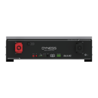
Table 2-7 LED Status Indicators
Battery
Status
SOC(%)
LED1
LED2
LED3
LED4
LED5
ALM
RUN
Shutdown
/
off
off
off
off
off
off
off
Standby
80%≤SOC≤100%
off
Flashing
60%≤SOC80%
off
off
Flashing
40%≤SOC
60%
off
off
off
Flashing
20%≤SOC40%
off
off
off
off
Flashing
0%SOC20%
off
off
off
off
off
Flashing
SOC=0
off
off
off
off
off
off
Flashing
Charging
80%≤SOC≤100%
Flashing
off
Flashing
60%≤SOC
80%
Flashing
off
off
Flashing
40%≤SOC60%
Flashing
off
off
off
Flashing
20%≤SOC40%
Flashing
off
off
off
off
Flashing
0%SOC20%
Flashing
off
off
off
off
off
Flashing
SOC=0
Flashing
off
off
off
off
off
Flashing
Discharging
80%≤SOC≤100%
off
60%≤SOC80%
off
off
40%≤SOC
60%
off
off
off
20%≤SOC40%
off
off
off
off
0%
SOC
20%
off
off
off
off
off
SOC=0
off
off
off
off
off
off
A special ALM light flashing state: when the communication between batteries is lost or
abnormal,all the lights from SOC to RUN of the master battery will flash together.
means green light always on
means red light always on
Flashing: means green light flashing or red light flashing

Related product manuals