DL5.0C User Manual
©Dyness reserves the copyright of this document
4 Use, Maintenance and Troubleshooting
Battery System Usage and Operation Instructions
After completing the electrical installation, follow these steps to start the battery system.
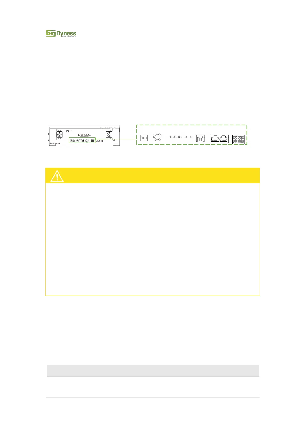
Refer to P7 DIP Switch Description to prepare the battery module before starting up, then
press the ON/OFF button to the ON position, press and hold the SW button for 3
seconds.
After the indicator self-test, the RUN indicator will light and the SOC indicator will be on
Figure 4-1
After pressing the power button, if the battery status indicator on the front panel
continues to be red, please refer to the "P24 Alarm description and processing ". If the
failure cannot be eliminated, please contact the dealer timely.
Use a voltmeter to measure whether the voltage of the circuit breaker battery access
terminal is higher than 44.8V, and check whether the voltage polarity is consistent with
the inverter input polarity. If the circuit breaker battery input terminal has a voltage
output and is greater than 44.8V, then the battery begun to work normally.
After confirming that the battery output voltage and polarity are correct, turn on the
inverter, close the circuit breaker.
Check if the indicator of the inverter and battery connection (communication indicator
and battery access status indicator) is normal. If it is normal, successfully complete the
connection between the battery and the inverter. If the indicator light is abnormal,
please refer to the inverter manual for the cause or contact the dealer.
Alarm Description and Processing
When protection mode is activated or system failure occurred, the alarm signal will be
given through the working status indicator on the front panel of the DL5.0C. The network
management can query the specific alarm categories.
If the fault such as single cell over voltage, charging over-current, under-voltage
protection, high-temp protection and other abnormalities which affects the output,
please deal with it according to Table 4-1.
Table 4-1 Main Alarm and Protection
Stop charging and find out the
cause of the trouble