DL5.0C User Manual
©Dyness reserves the copyright of this document
2. After the whole system connection, set the master DIP mode according to the inverter
model firstly, then start the battery.
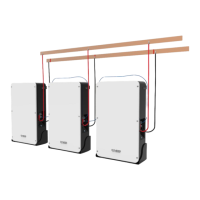
3. The BAT-INV comms cable is from inverter comm port to master CAN IN port, BAT-BAT
cable is from master CAN OUT to slave1 CAN IN, slave1 CAN OUT to slave2 CAN IN…
4.The limited continuous current for each pair of power cable is 120A. Please add power
cable according to the proportion if the max. working current of the inverter is more than
120A.
Battery parameter settings on the inverter
Max Charging(Bulk) Voltage: 56.5V
Absorption Voltage: 56V
Float Voltage: 55.5V
Shut Down(cut off) Voltage: 48~50V
Shut Down(cut off) SOC: 20%
Restart Voltage: 52V
Max Charge Current: 50A*battery QTY
Max Discharge Current: 50A*battery QTY
Register on the website after installation
After the battery system installation is completed and the running is normal, you need to
log in to the DYNESS official website to register the product installation and use
information to make the product warranty effective. Please follow the instructions on the
website to register.
http://www.dyness-tech.com/ Service Sign Up
 Loading...