2. The cardboard must be perpendicular to the ground while drawing the holes.
3. The bottom of the cardboard is about 300mm from the ground.
4. According to the position of the mark, 8 holes in diameter 10mm and depth of
more than 70mm are hit on the wall with an electric drill, which are used for fitting
expansion bolt M6.
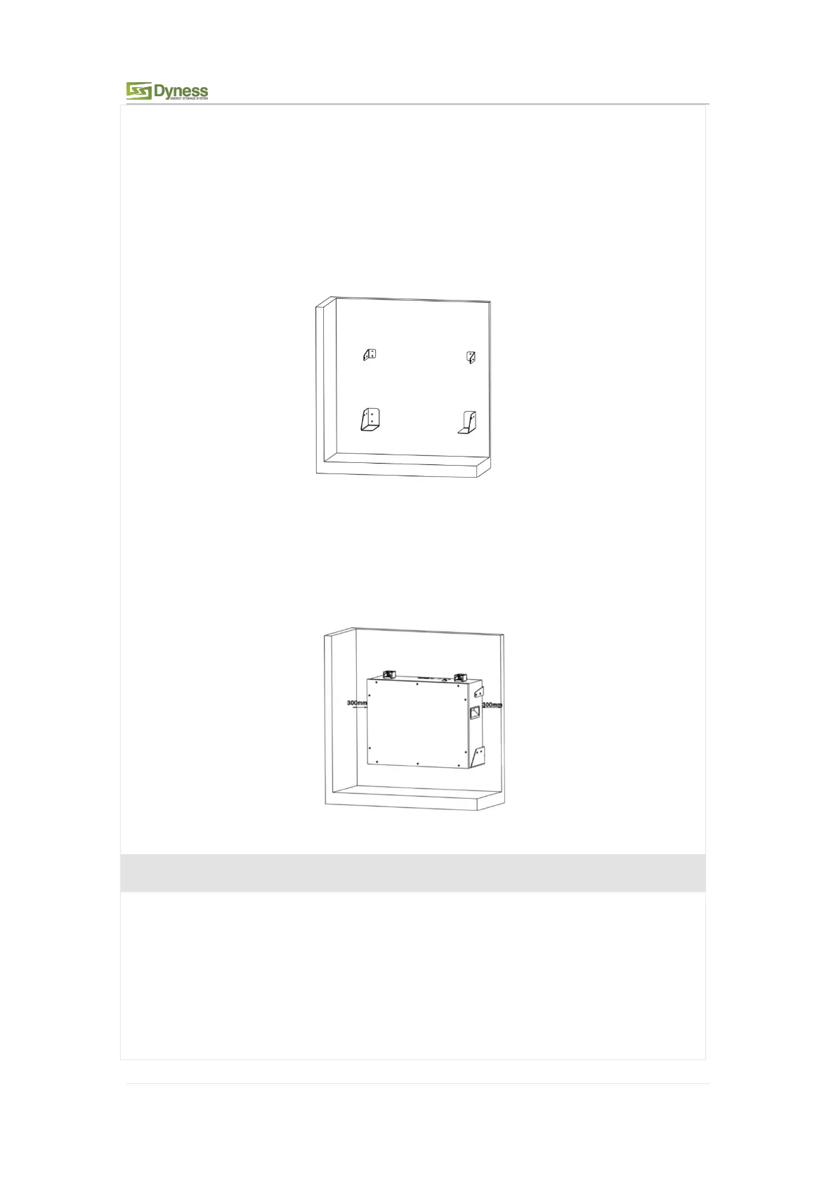
5. Fixing the expansion bolt M6 into the bottom of the hole on the wall, and fix the
Support bracket and Battery bottom bracket on the wall with M6 bolts. Twisting
force keeps 9.8N·m.
Figure 3-9
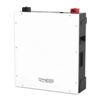
6. Carry or hoist the battery box to the installed Battery bottom bracket. Fixing the
Support bracket and the upper part of the battery box with M6 bolts, twisting
force keeps 9.8N·m.Then fixing the Battery bottom bracket and the bottom part of
the battery box with M6 bolts. Twisting force keeps 9.8N·m.
Figure 3-10
When the battery system is placed directly on the ground, a fixed support must be
used to fix the top of the battery box on the wall
1
.
Use the positioning cardboard (provided in accessory package) and mark the screw
hole positions on the wall, as shown four holes in the picture on the left.