DL5.0C User Manual
©Dyness reserves the copyright of this document
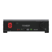
Table 2-3 Interface Definition
OFF/ON, must be in the "ON" state when in use
Battery output positive or parallel positive line
SW (battery
wake/sleep
switch)
When the "OFF/ON" switch button is in the ON state,
press and hold this button for 3 seconds to put the
battery into the power-on or off state.
The number of green lights shows the remaining power.
Table 2-3 for details.
Red light flashing when an alarm occurs, red light always
on during protection status. After the condition of trigger
protection is relieved, it can be automatically closed.
Green light flashing during standby and charging mode.
Green light always on when discharging.
Communication cascade port, support RS232
Communication cascade port, support CAN/ RS485
communication (factory default CAN communication)
Battery output negative or parallel negative line
Table 2-4 DIP switch definition and description
DIP switch position (master communication protocol and baud rate selection)
Define different protocols;
Distinguish between master and slave
When the batteries are connected in parallel, the host communicates with the slaves
through the CAN interface. The host summarizes the information of the entire
battery system and communicates with the inverter through CAN or 485.
If the master is the latest DL5.0C battery with DIP switch:
1. The communication cable from the master CAN IN to the inverter comm port
should be the correct one.