Tower ESS Unit User Manual
18
1.The environment is meeting all technical
requirements: “3.1.1~3.1.6”
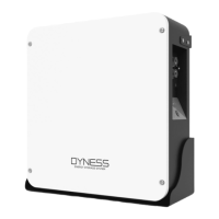
1. Determine Tower placement
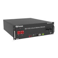
3. Install battery module
1. Battery system grounding (After the HV9637
module is stacked up and down, it is fixed by two
screws on the left and right sides. After the screw is
fixed, the shell surface of the upper and lower
modules is fixed and contacted together through
screws.There is a special docking point at the bottom
of the battery base. Please refer to the 3.6.3.1 )
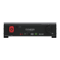
1. Switch on the DC breaker of the BDU
2. Switch on the “POWER ON” switch
3. Press the “POWER WAKE” button for about 3S
4. Check the system output voltage
5. Shut down the battery system
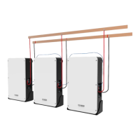
1. Connect External Power Cable to the inverter
2. Connect the EXT-CAN communication cable to
the inverter
3.6.1 Installation preparation
1. Make sure the environment is meeting all technical requirements: “3.1.1~3.1.6”
2. Prepare equipment and tools for installation.
3. Confirm that the DC breaker is in the OFF state to ensure that it is no live operation.
3.6.2 Mechanical installation
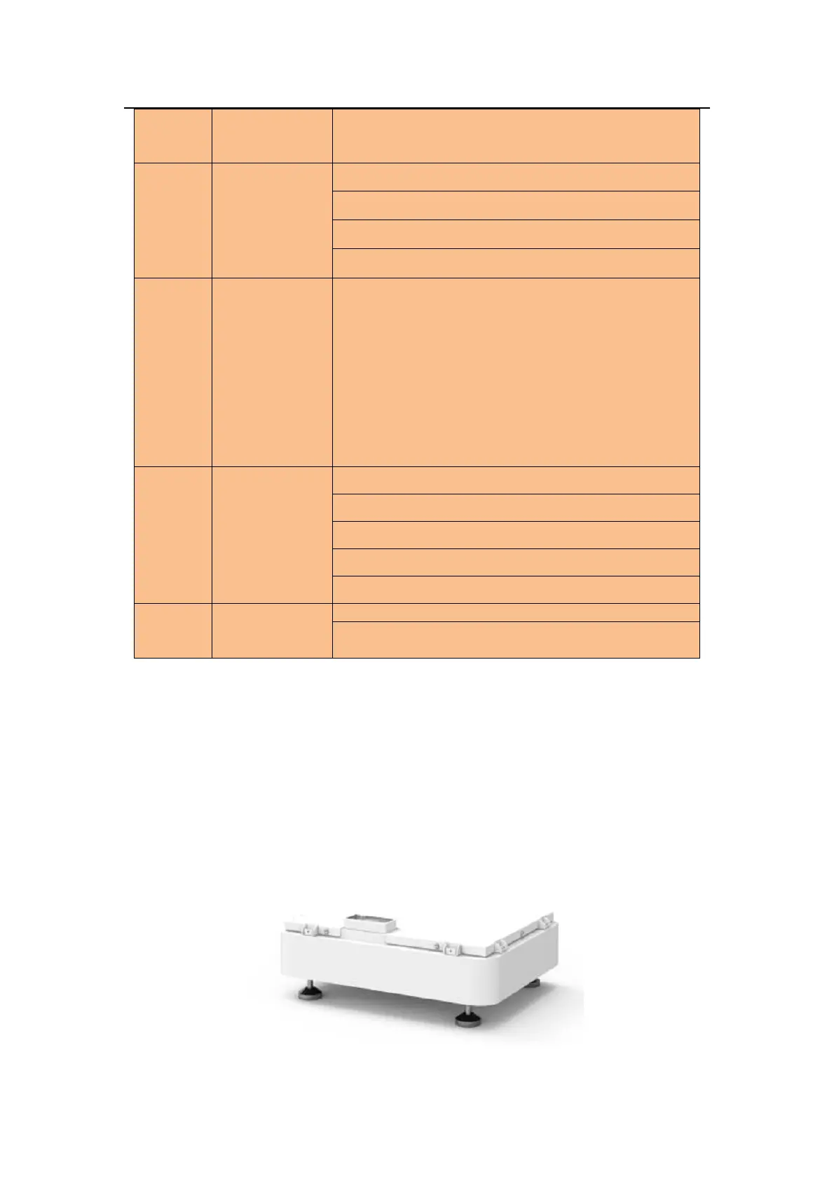
3.6.2.1 Place the base
● Choose a appropriate place to set base.
3.6.2.2 Battery module installation