55" 120Hz 1080p LCD HDTV
QUICK SETUP GUIDE
DX-55L150A11
Remote control
and
2 AAA batteries
TV stand and screws
Quick Setup Guide
INPUT
ENTER
EN-31203B
HDMI
AUDIO
PICTURE
MENU
CH
VOL
MUTE
VIDEO
COMP
VGA
ZOOM
EXIT
TV
1
2
3
6 5 4
7 8 9
0
RECALL
GUIDE
INFO
MTS/SAP
CCD
TIME
SLEEP
HDMI cable
(not included)
HDMI device
Back of TV
Component video device
Back of TV
Component video cable
Composite
cable
WE ARE GOING GREEN!
A copy of the manual is not provided in the box but
is available at www.dynexproducts.com
Click Service & Support, enter your model number
in the Product Search eld, then click Search.
Home theater
system
Digital coaxial cable
Back of TV
Audio cable
Digital audio
out
Back of TV
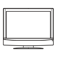
Front and side features
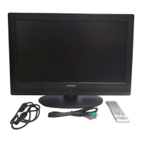
Installing the stand
1 Remove the stand from the box and place it on a table or bench.
2 Lay the TV on a at, cushioned surface.
3 Align the base with the bottom of the TV, then secure the base to the TV
with the six screws provided.
Installing a wall-mount bracket
1 Carefully place your TV screen face-down on a cushioned, clean surface to
protect the screen from damages and scratches.
2 Remove the pedestal stand. See “Removing the stand” in your User Guide.
3 Secure the wall-mount bracket to the back of your TV using the four screws
provided with the bracket.
Connecting a DVD or Blu-ray DVD player, cable
box, satellite receiver, or game station
Using HDMI (best)
Using component (better)
Note: Cable connectors and jacks are often color-coded. Match the colors when
you connect the component video and AV cables.
Using composite (good)
Note: Cable connectors and jacks are often color-coded. Match the colors when
you connect the composite AV cable. A composite jack is also available on the
back panel of the TV.
Philips
PHDVD5, PH5DSS,
PMDVR8, PDVR8
115
DirectTV
RC23
10463
RCA
RCU807
135
One for All
URC-6690
0464
Sony
RM-VL600
8043
Comcast
M1057
0463
Dish Network
VIP508, VIP622
720
Motorola
DRC800
0463
TIVO
Series 3, HD
0091
Universal remote control makers and models Set-top box makers and models
Universal remote control TV codes (for all Dynex TVs manufactured after Jan. 1, 2007)
Power
indicator
Remote control
sensor
Composite audio/video
cable
N
Video device
Back of TV
Connecting an antenna
Connect a 75 ohm cable (not included) to the ANT/CABLE jack on the back of
your TV and the RF OUT jack on the antenna.
Connecting a home theater system
Using digital audio:
Note: The DIGITAL OUTPUT jack only works with digital TV channels. Please refer
to the User Guide for information on connecting to a home theater system using
analog (stereo) audio or when using an HDMI device.
Connecting power
Connect the power cable to a power outlet.
Setting up your remote control
1 While pressing the release button on the battery compartment cover on the
back of the remote, lift the cover o the remote.
2 Insert two AAA batteries into the battery compartment. Make sure that the +
and – symbols on the batteries align with the + and – symbols in the battery
compartment.
3 Replace the cover. Make sure that the lock snaps into place.
To program your existing remote control to work with your Dynex TV, see the
table below for common codes. If you have problems programming your remote,
or need a dierent remote control code, visit www.dynexproducts.com
for the latest remote control code information.
Click Service & Support, select Find my remote control code, enter model
number in the Product Search eld, then click Search. Remote control codes are
near the bottom of the page.
For step-by-step instructions on programming the remote control, see your
User Guide.
Antenna cable
Three HDMI jacks are also
available on the back panel
of the TV.
A component jack is also
available on the back
panel of the TV.