EasyManua.ls Logo

Dynojet Power Commander III USB 109-411 User Manual

Dynojet Power Commander III USB 109-411
5 pages
To Next Page IconTo Next Page
Page #1 background imageLoading...
Page #1 background image
i109-411 VTX 1800 - PCIII USB - 1
2002-2004 Honda VTX 1800C
Installation Instructions for:
Dynojet Research 2191 Mendenhall Drive North Las Vegas, NV 89081 (800) 992-4993 www.powercommander.com
Parts List
1 Power Commander
1 USB Cable
1 CD-ROM
1 Installation Guide
1 Power Adapter
2 Wire Tap
1 Power Wire
2 Power Commander Decals
2 Dynojet Decals
1 Velcro
®
Strip
1 Alcohol Swab
You can also download the Power
Commander software and latest maps
from our web site at:
www.powercommander.com
The ignition MUST be turned
OFF before installation!
PLEASE READ ALL DIRECTIONS BEFORE STARTING INSTALLATION
Button Adjustment Display
Faceplate Buttons
Expansion Port
USB Port
2002-2003 Honda VTX 1800R
For 04-07 R & N model use 122-411
For 05-07 F & C model use 122-411
Question and Answer IconNeed help?

Do you have a question about the Dynojet Power Commander III USB 109-411 and is the answer not in the manual?

Dynojet Power Commander III USB 109-411 Specifications

General IconGeneral
ModelPower Commander III USB
Part Number109-411
TypeFuel Management System
ConnectionUSB
AdjustabilityFully Adjustable
CompatibilityVarious Motorcycle Models
SKU109-411
USB ConnectivityYes
BrandDynojet
Product NamePower Commander III USB
InstallationPlug and Play
Connector TypeOEM

Summary

Power Commander Installation Guide

Parts Included

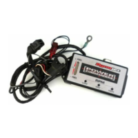
Lists all components provided in the Dynojet Power Commander installation kit.

Critical Installation Precautions

Emphasizes essential safety steps, including turning off ignition before starting.

ECU and Ground Wire Connections

Disconnecting Stock ECU Connector

Step-by-step guide to disconnect the main ECU connector from the motorcycle.

Attaching Ground Wire

Instructions for connecting the Power Commander's ground wire to the vehicle frame.

Wiring Harness Integration

ECU Wire Tap Installation

Details connecting the PCIII's gray wire to the ECU using a supplied wire tap.

Locating Main Wire Cluster

Guidance for identifying a specific wire cluster beneath the right side cover.

Power and Mounting Procedures

Connecting Tail Light Power

Connecting the PCIII's red wires to the tail light power source for operation.

Mounting the Power Commander Unit

Routing the unit and securing it to the battery box using supplied Velcro.

European Model Specific Wiring

European Power Lead Connection

Specific instructions for connecting the power lead and wire tap on European bikes.

European Power Supply Notes

Considerations for tail light power and potential stalling on European models.

Related product manuals