Do you have a question about the Dynojet Power commander 3 and is the answer not in the manual?
Remove seat, side covers, fuel tank, and air box before installation.
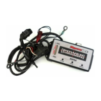
Route and connect PCIII harness to injectors and throttle position sensor.
Route ground wire to battery and secure the PCIII unit under the seat.
Connect and ground the O2 eliminator harness to the stock wiring.
Secure PCIII with velcro and reinstall fuel tank, fairing, and seats.
| Fuel Adjustment | Yes |
|---|---|
| Input Voltage | 12V |
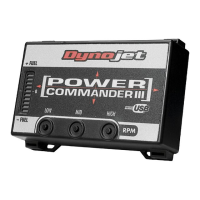
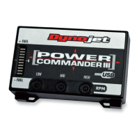
| Type | Fuel Injection Module |
| Computer Connectivity | USB |
| Software | Power Commander Software |
| Compatible Models | Varies by model |
| Maps | Pre-loaded and customizable |