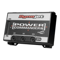
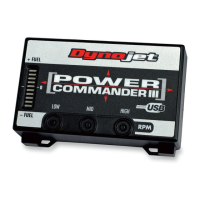
25-010 www.powercommander.com 11-12 CanAm Spyder RT PCV - 2
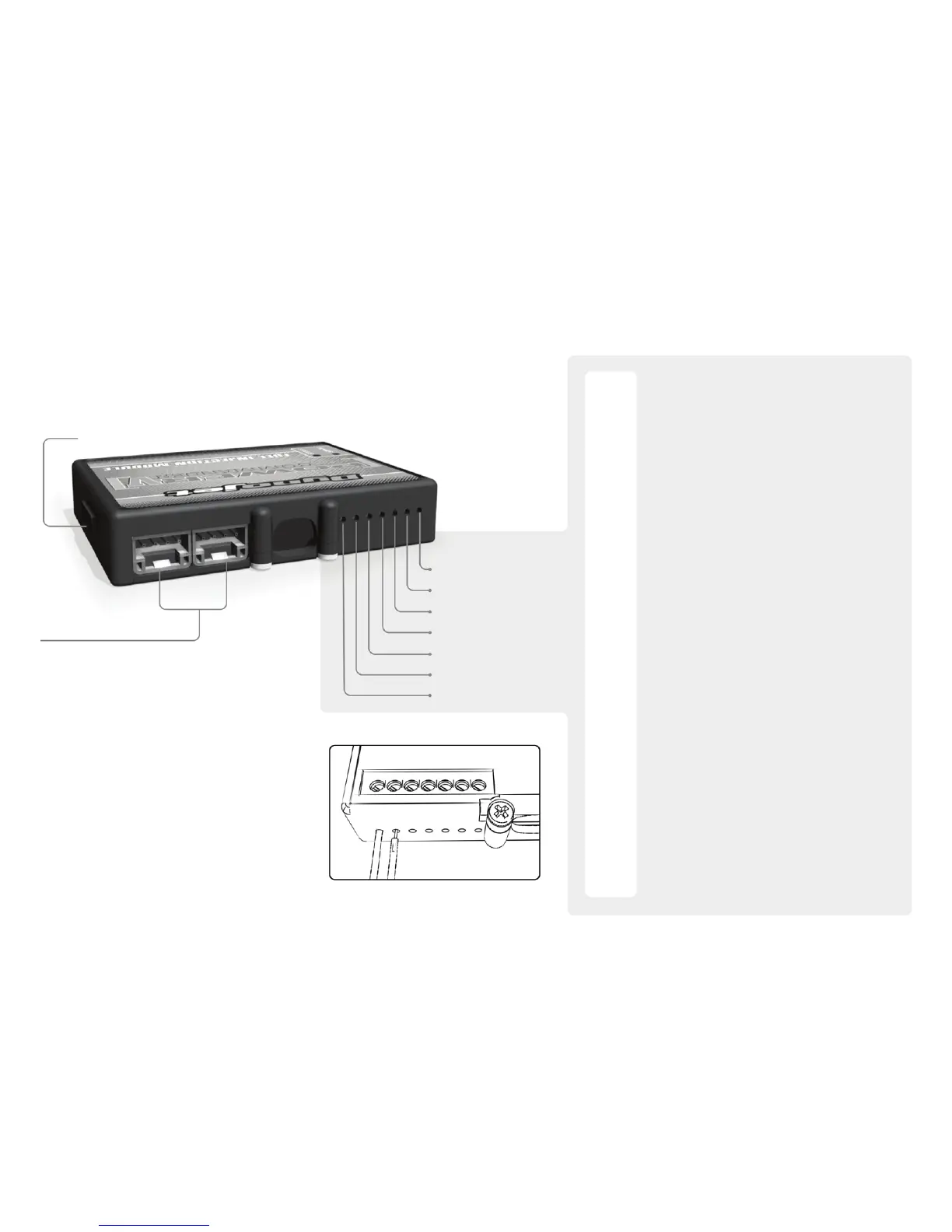
EXPANSION PORTS 1 & 2
Optional Accessories such as
Color LCD unit or Auto tune kit.
POWER COMMANDER V
INPUT ACCESSORY GUIDE
Map - The PCV has the ability to hold 2 different
base maps. You can switch on the fly
between these two base maps when you hook
up a switch to the MAP inputs. You can use
any open/close type switch. The polarity of
the wires is not important. When using the
Autotune kit one position will hold a base map
and the other position will let you activate the
learning mode. When the switch is “CLOSED”
Autotune will be activated.
Shifter- These inputs are for use with the Dynojet
quickshifter. Insert the wires from the Dynojet
quickshifter into the SHIFTER inputs. The
polarity of the wires is not important.
Speed- If your application has a speed sensor then
you can tap into the signal side of the sensor
and run a wire into this input. This will allow
you to calculate gear position in the Control
Center Software. Once gear position is setup
you can alter your map based on gear position
and setup gear dependent kill times when
using a quickshifter.
Analog- This input is for a 0-5v signal such as
engine temp, boost, etc. Once this input
is established you can alter your fuel curve
based on this input in the control center
software.
Launch- You can connect a wire to either input 1B or
2B and then the other end to a switch. This
switch when engaged (continuity) will only
allow the RPM to be raised to a certain limit
(Set in the software). When released you will
have full RPM.
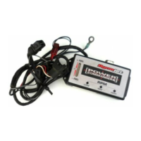
ACCESSORY INPUTS
Wire connections:
To input wires into the PCV first remove the rubber
plug on the backside of the unit and loosen the
screw for the corresponding input. Using a 22-24
gauge wire strip about 10mm from its end. Push the
wire into the hole of the PCV until is stops and then
tighten the screw. Make sure to reinstall the rubber
plug.
NOTE: If you tin the wires with solder it will make
inserting them easier.
N/A
ANALOG
SPEED
INPUT 1
INPUT 1
INPUT 2
INPUT 2
USB CONNECTION