EasyManuals Logo

Dynojet Power commander V User Manual

Dynojet Power commander V
8 pages
To Next Page IconTo Next Page
To Previous Page IconTo Previous Page
Page #5 background imageLoading...
Page #5 background image
25-010 www.powercommander.com 11-12 CanAm Spyder RT PCV - 5
14 Plug the YELLOW colored wires from the PCV in-line of the stock wiring
harness and injector.
Reinstall MAP sensor to throttle body.
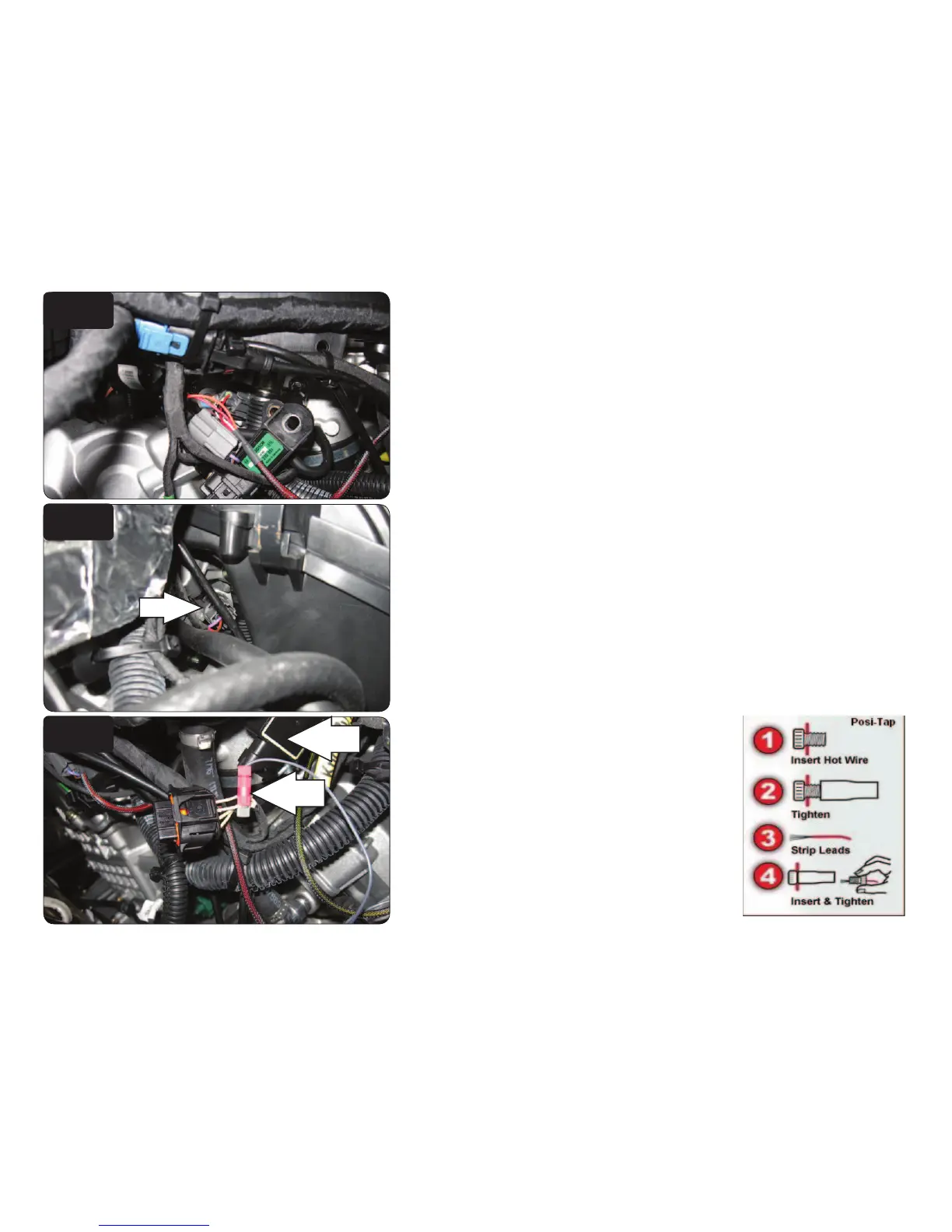
15 Unplug the stock wiring harness from the injector on the right hand side
(Fig. H).
This connection is located to the Right, Rear of the air box.
16 Plug the ORANGE colored wires of the PCV in-line of the stock wiring harness
and injector.
17 Locate the Throttle Position Sensor on the left
side of the throttle bodies.
18 Use the supplied Posi-tap to attach the GREY
wire of the PCV to the YEL/WHT wire of the TPS
wiring harness.
Figure J is shown with the TPS harness
disconnected from the sensor. Make sure to
reconnect the harness to the sensor.
FIG.G
FIG.H
FIG.J
Posi tap
TPS

Other manuals for Dynojet Power commander V

Questions and Answers:

Question and Answer IconNeed help?

Do you have a question about the Dynojet Power commander V and is the answer not in the manual?

Dynojet Power commander V Specifications

General IconGeneral
Fuel ControlYes
Rev XtendYes
USB ConnectivityYes
SoftwarePower Commander Software
SizeCompact
Quick Shifter InputYes
Analog InputYes
Map SwitchingYes
Power Supply12V DC
Weight0.5 lbs
Warranty1 year
Ignition ControlYes
Auto-tuneOptional
Operating Temperature85°C
Adjustable ParametersFuel, ignition
CompatibilityVarious motorcycle models

Related product manuals