PFD Operation
4-10 SkyView SE Pilot’s User Guide - Revision B
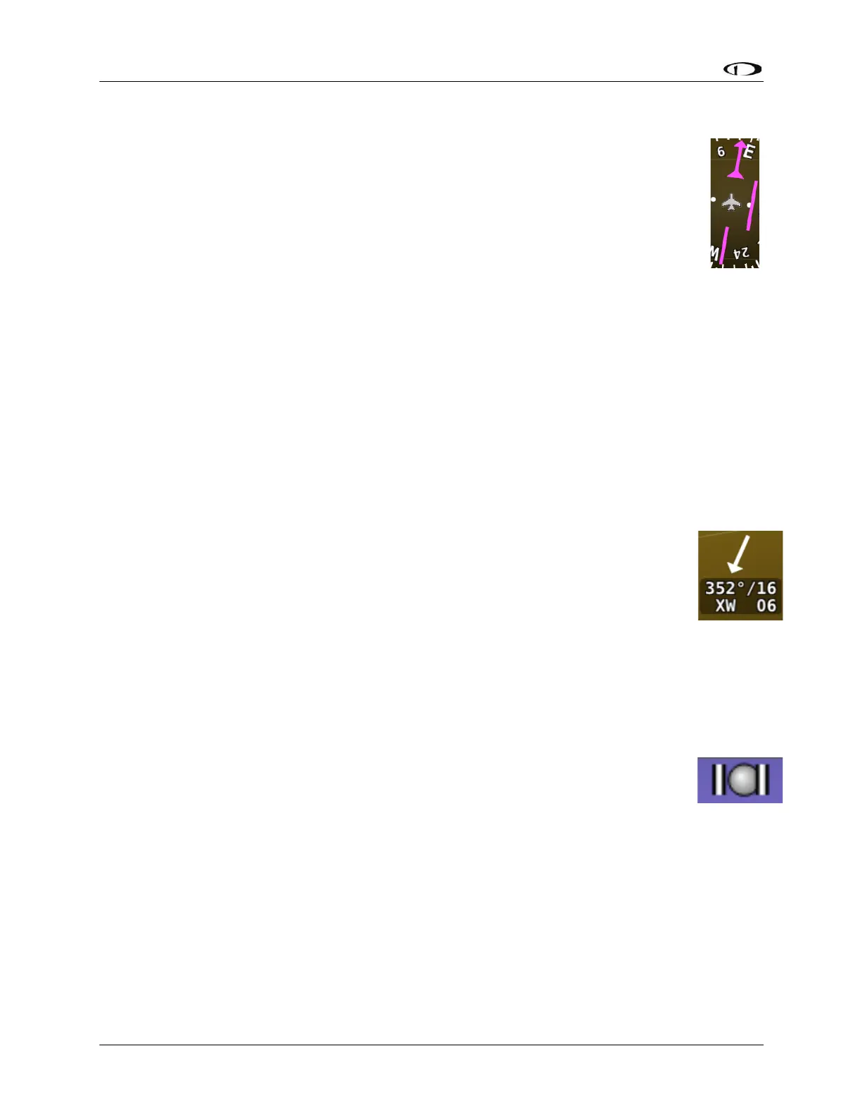
Course Needle and Course Deviation Indicator (CDI)
The course needle is a magenta line with an arrow at its end which points to the
course defined by the external GPS navigator.
The Course Deviation Indicator (CDI) is the middle section of the course needle. When
the aircraft is not precisely positioned on the indicated course, that middle bar will
slide left or right to indicate the location of the intended course relative to the
aircraft’s position. If the CDI bar is to the right of the course needle, the intended
course is to the right of the aircraft’s current position.
When following a GPS course, a full scale deflection of the bar represents 5 nautical miles of
deviation. When on course, the course indicator and the CDI make a solid line, making it easy to
see when there is little error in your aircraft's position. Unlike a CDI indicator found in basic
aircraft, the CDI needle on an HSI rotates with the heading indicator and course indicator. By
turning the aircraft towards the CDI needle you reduce your deviation.
Wind Vector
Wind vector information is located just above the OAT display on the PFD. The winds aloft
arrow indicates the wind direction relative to your current direction of flight. The
wind strength, direction, and cross wind component are also textually provided. If
SkyView SE cannot make an accurate winds aloft calculation, the arrow is not
displayed and the numbers are replaced by dashes. The display of winds aloft
requires an active GPS connection and an OAT probe. In very light winds, the wind
speed number is not displayed, although the arrow is. Note that due to a limitation
in the SV-GPS-250 and SV-GPS-2020 hardware, winds information will not be
available above 415 knots ground speed if it is being used as the GPS source. The
Wind Vector will not appear if the SV-ADAHRS-200/201, SV-MAG-236, GPS, or OAT is not
functional.
Slip/Skid Ball
The action of the slip/skid ball simulates an analog slip/skid ball and provides a visual
representation of lateral acceleration. When the ball is within the two vertical lines,
the aircraft is in coordinated flight. Figure 21 is an example SkyView SE slip/skid ball.