service manual
2
3
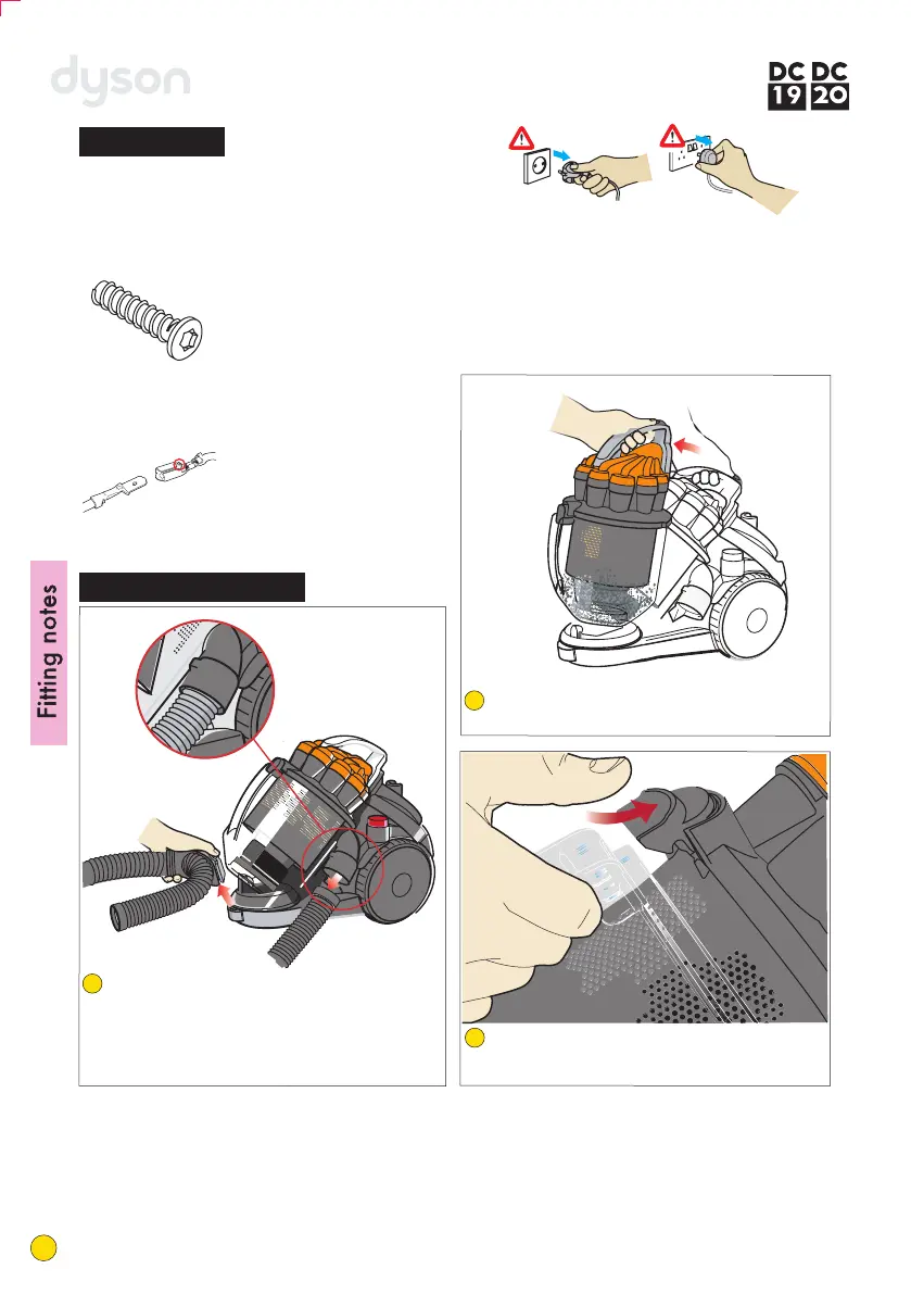
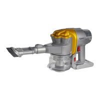
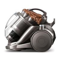
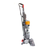
Press the release catch to remove the cyclone
and bin assembly from the product.
1
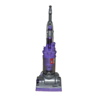
Unclip the wand assembly from the side of the
cyclone assembly and unwrap the hose assembly
from around the product (DC20 only). Remove
the end of the hose from the inlet on the side of
the product. Unclip the retaining bracket and
remove from the front of the machine.
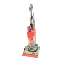
If necessary the bin can be removed from the
cyclone assembly by pressing the bin release
catch.
All screws used in DC19 and
DC20 are M3.5 x 16 Torx T-15
unless otherwise stated.
Some female terminal clips
used in DC19 and DC20
contain a lock mechanism.
The mechanism will need
to be pressed before
separation from the male
terminal can occur.
3
Before attempting any repairs it is vital to
ensure the product is totally isolated from the
mains supply and that accidental reconnection cannot occur.
General notes
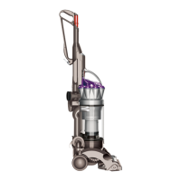
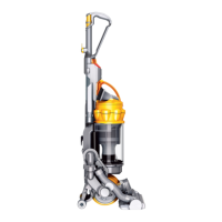
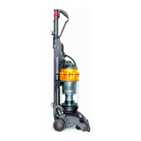
Main body - dismantle
Unclip the post filter cover catch using a flat bladed
screwdriver. Carefully remove the cover and filter.
Unclip the pre-filter cover from the locating point
on the upper motor cover (UMC). Pull the pre-filter
cover away from the machine until it releases from
the hinge points. Remove the pre-filter assembly.
Firmly pull the wheels away from the main body.
Remove the six screws from the UMC. Pull the cable out slightly and lift the UMC off the Lower Motor Cover
(LMC).
Fitting notes
2
4
7
6
5
4
service manual