E8500 Instruction & Operations Manual
version 1.010
Page 13 of 45
CHAPTER 3
BASIC INSTRUMENT OPERATION
It is possible to master the basic operation of the instrument in a few minutes by
following the procedure outlined below. Please refer to the other sections of this manual
for a description of the more advanced features.
The E8500 emissions analyzer consists of the following three major components:
1. The probe sampling line, whose function is to extract the sample, sense
the stack temperature and depending on the option measure the stack gas
velocity
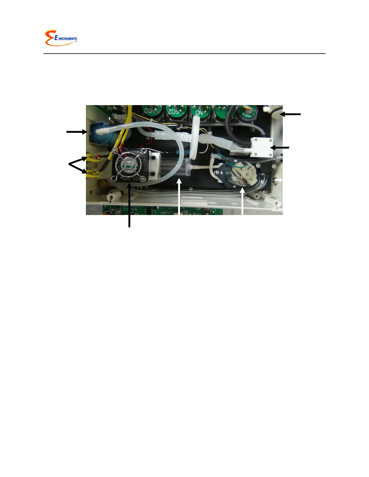
2. The conditioning system is located inside the analyzer’s drawer
compartment and consists of the thermoelectric chiller, automatic
condensate draining system, and filters
3. The main section of the analyzer that houses all the gas sensors, battery
pack, and PC board
To operate the instrument, follow the steps outlined below.
1. Turn the analyzer on. The instrument pump will immediately turn on and the E
INSTRUMENTS logo will appear. Press OK to run the autozero cycle.
2. Attach the probe and sampling line that is supplied with your analyzer.
3. If you are using the analyzer for the first time,
press the SETUP key to set the appropriate
parameters (i.e. fuel, units, etc.) for your
application. See Chapter 7 for an explanation of
each parameter. A table of the SETUP display is
shown here.
APR 1 ‘11 12:45:00
Fuel: NATURL GAS
Temperature Units: F
Measure Units: PPM
Pressure Units: inWC
O2 Reference: TRUE
Pumps: OFF
Dilution Duty: 100%
Water Drain: 5min
Chiller Duty: 50%
Dilute CO: 4000 PPM
Use CO-IR: 9000 PPM
Thermal Eff: 0.30
Display Contrast: 24
Baudrate: 9.6 k
Version: 1.0
Battery: x.xx V