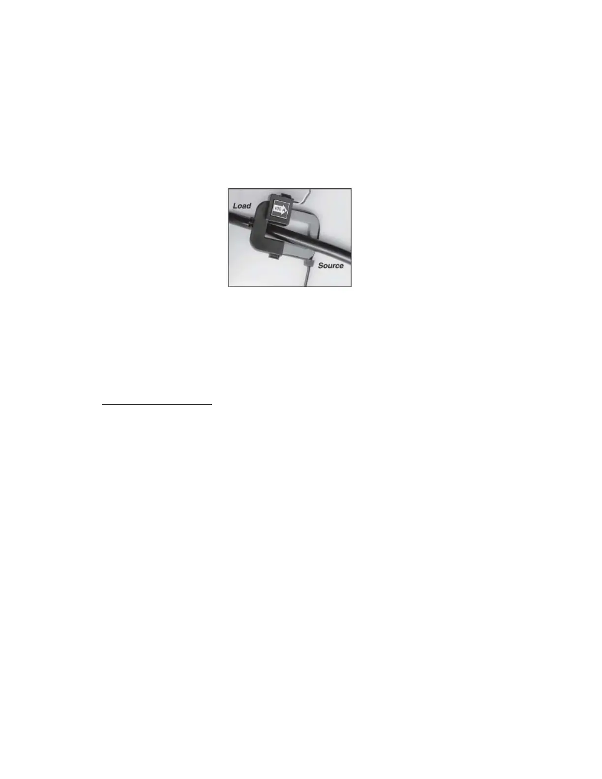
STEP 2 : Reassemble the current sensor assembly around the conductor(s) to
be monitored. Ensure the current sensor halves marked “Load’’
are both facing the load side of the conductor. The colored arrow
will be on the source side of the conductor being monitored and
MUST be pointed in a clockwise direction around the conductor
being monitored. Tighten the nylon clamp to complete the assembly.
IMPORTANT: When looking from the source side of the conductor(s)
being monitored, you should see the arrow on the current
sensor assembly. The arrow should be pointing in a
clockwise direction around the conductor(s) being
monitored. lf the arrow is not positioned on the source
side, inaccurate readings will result.
Current Sensor Wiring
Once all the current sensors are installed onto their appropriate phase
conductors, you can begin terminating the current sensors onto the
E-Mon D-Mon® Green Class Net Meter
Main Board.
The current sensor leads can be extended up to 500 feet for remote
monitoring applications. To extend the length of the wires, use
#22 AWG twisted pair wire with a black and white conductor, rated for
600VAC.
The Current Sensor connection points are located on the bottom
center of the Main Power Board. Three removable plugs exist, one for
each Current Sensor Phase Input. The Header portions of the
connectors are labeled TB2, TB3, and TB4. Silkscreen located in
front of each connector instructs you which terminal of the plug is for
the white conductor and which terminal is wired to the black conductor.
Once each current sensor is wired to its respective plug, insert
each plug into the appropriate header.
Page 12