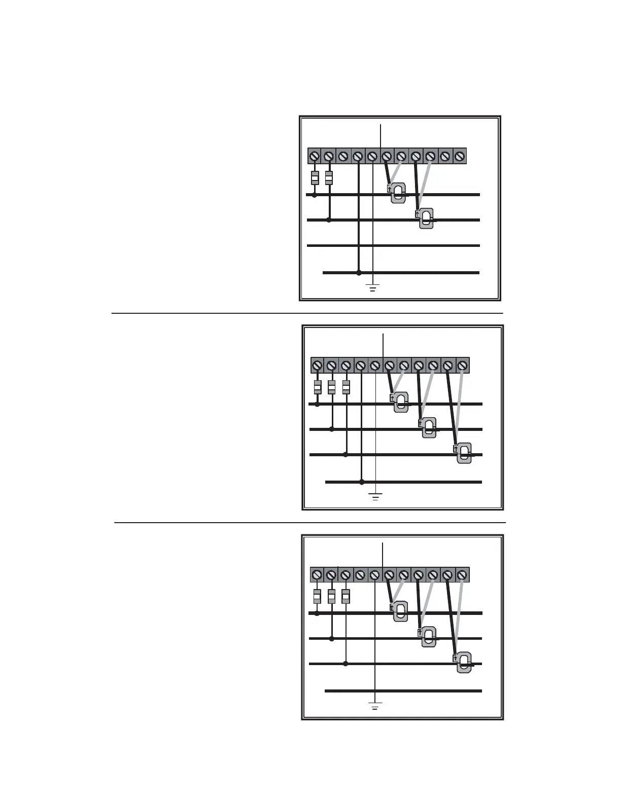
5.4 MAINS Line Voltage and Current Sensor Wiring Diagrams
Page 13
Line Voltage Connections: # 14-22 AWG
Sensor Connections: B = Black Lead
W = White Lead
*1/10 A , 600 VAC inline fuse per conductor.
Littlefuse part number KLDR
.100.
** Neutral not used in delta system.
Remove neutral terminal block screw for
Delta Systems.
LOAD
LINE VOLTAGE CURRENT SENSORS
A
B
C
N
∅A ∅B ∅
C
N G B W B W B W
∅A ∅B ∅ C
**
*
3-Phase, 3-Wire Installation Diagram
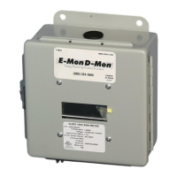
Line Voltage Connections: # 14-22 AWG
Sensor Connections: B = Black Lead
W = White Lead
* 1/10 A, 600 VAC inline fuse per conductor.
Littlefuse part number KLDR
.100.
** Neutral not used in delta system.
Remove neutral terminal block screw for
Delta systems.
LOAD
A
B
C
N
∅A ∅B ∅ C N G B W B W B W
∅A ∅B ∅ C
*
**
3-Phase, 4-Wire Installation Diagram
SOURCE
SOURCE
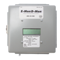
Line Voltage Connections: # 14-22 AWG
Sensor Connections: B = Black Lead
W = White Lead
* 1/10 A, 600 VAC inline fuse per conductor.
Littlefuse part number KLDR
.100.
** Neutral not used in delta system.
Remove neutral terminal block screw for
Delta systems.
LOAD
A
B
C
N
∅A ∅B ∅ C N G B W B W B W
∅A ∅B ∅ C
*
*
Single Phase, 3-Wire Installation Diagram
SOURCE
Test Equipment Depot - 800.517.8431 - 99 Washington Street Melrose, MA 02176
TestEquipmentDepot.com