Installation, Operation and Parts Manual
EE62C-35T-E / EE62C-42T-E
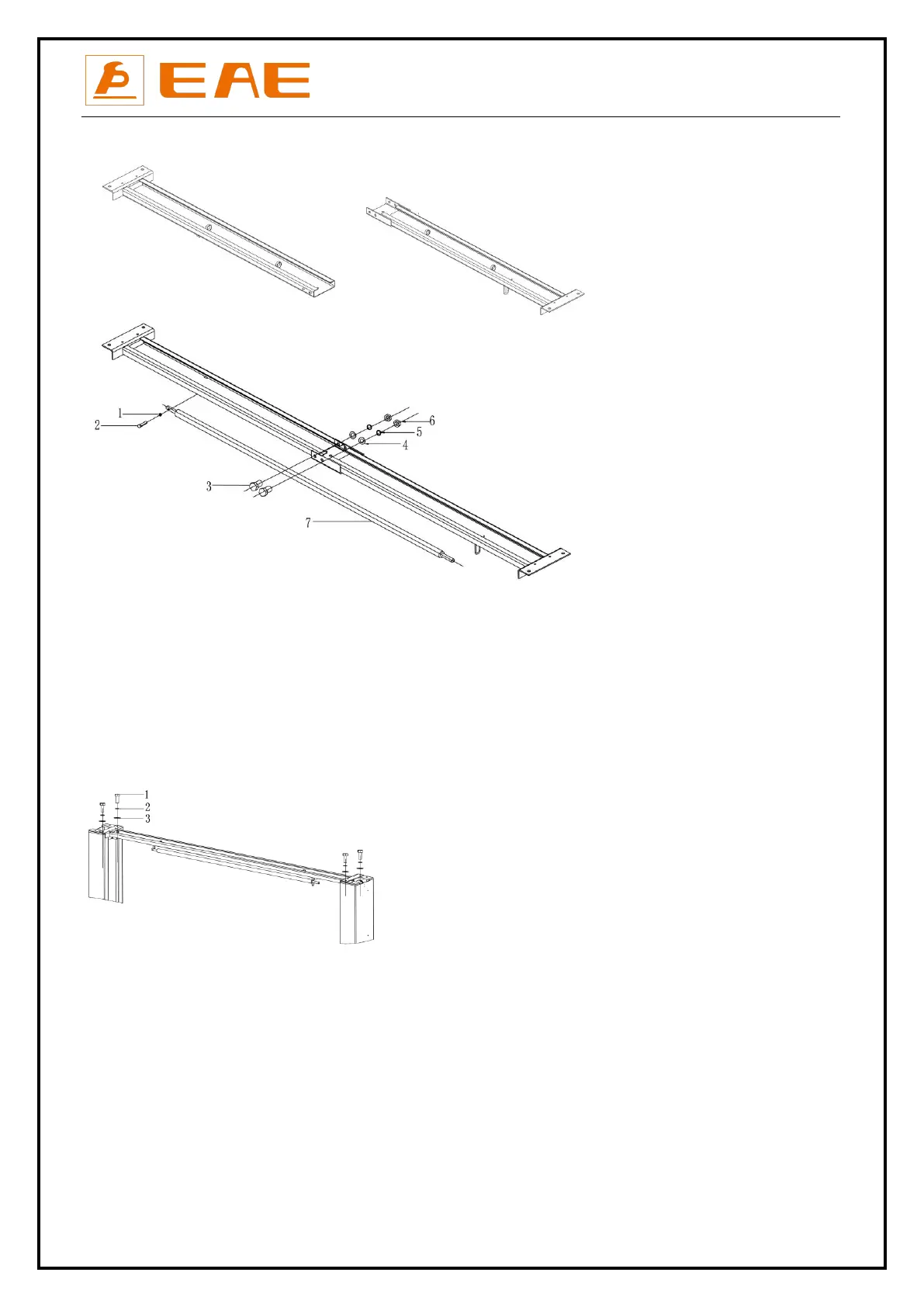
2. Connect the beams and fix the roof protection bumper
Step 5: Fix the standing position for the two posts. (See Annex 1, floor plan)
1. Unfold the package and decide on which post the power unit will be mounted.
2. Draw an outline of the base plate on the ground with chalk and ascertain the position for the post.
Step 6: Connect cross beam.
Make the posts face to each other and the distance between the posts equals to the length of the overhead crossbeam. Fix the beam
to the posts by screw M12×30
Step 7: Erect and secure the post.
1. Make the posts face to each other and the distance between the posts equals to the length of the base plate. Use proper means to
erect the post.
2. Use suitable means to raise the lifting carriage to the first latching position. All the mounting holes in the base plate are then
accessible. Make sure the locking pawl is engaged.
3. Check and align the position of the base plates again.
4. Drill the mounting holes. Remove the drilling dust from the hole.
5. Use a spirit level to check the vertical alignment of the posts. If necessary, place equalizing plates under the base plates.
6. Tighten the nuts. Torque: 80-100Nm.
2.Hex socket cylinder screw M6*35
7.Car roof protective rod