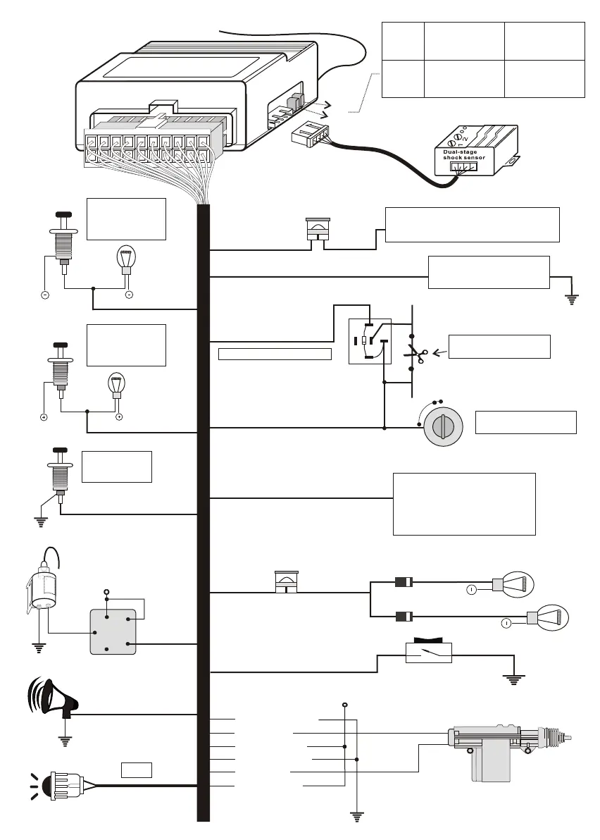
Antenna
Red (+)
Black(-)
2-side parking Lights
Connect to Red from Siren
LED
Connect to Chassis
Ground (-)
Connect to (+) 12Volts
Constant Battery Sources
15Amp Fuse
10Amp Fuse
9 8 7 6 5 4 3 2 1
10
20 19 18 17 16 15 14 13 12 11
J1
J2
J1
jumper
J2
jumper
With jumper Without jumper
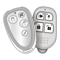
Door lock / unlock
0.8sec.
for normal car.
Door switch arming
delay 0sec. for
normal car.
Door switch arming
delay 30sec. for
Dome light delay
car.
Door lock / unlock
4sec. for air
compressor car.
(-) ground output when armed
Connect to Switched (+)
12Volts Ignition
Yellow(+)
O
C
N
C
A
S
F
T
F
O
30
85
86
87a
87
Orange(-)
Red from
Socket relay
ignition switch side
White from
Socket relay
starter solenoid side
Cut Existing low current
Start solenoid wire
Connect to
Hood or Trunk
Pin Switch
Connect to
Existing Negative
Door Pin Switch
(GM Type)
Connect to
Existing Positive
Door Pin Switch
(Ford Type)
86
85
87
87a
30
+12V
Optional relay
Trunk
release
solenoid
+12V
(-)Ground
Lock motor
Unlock motor
Clear green/black
Clear green
Clear green/red
Clear blue/black
Clear blue
Clear blue/red
Wiring diagram
Use 6A2 diode
Deep green (-)
Purple (+)
Deep blue (-)
Grey (-)
White (+)
Brown (+)
Plug-in shock sensor
Pink (-)
Immobilizer-1
Note: Disconnect the power from the main control unit
before setting the jumpers .
AUX. Channel programme output
Negative pulsed output
programmable feature.
1. Window close
2. Pager
3. 2nd immobilizer
Emergency reset switch(-) input
Black/white (-)
Plug in any OE switch
as long as it negative pulsed