EasyManua.ls Logo

Eaglemaster E8 User Manual

Default Icon
45 pages
To Next Page IconTo Next Page
Page #1 background imageLoading...
Page #1 background image
IMPORTANT:
Please read the entire manual for complete details on the features, accessories and
operation before attempting to use your security system.
This Security system must be installed by a qualified technician to ensure proper
operation. Do not attempt to install or modify this system yourself as
this way void your warranty.
2-WAY CAR ALARM SYSTEM
WITH REMOTE ENGINE START
MODEL
Question and Answer IconNeed help?

Do you have a question about the Eaglemaster E8 and is the answer not in the manual?

Eaglemaster E8 Specifications

General IconGeneral
BrandEaglemaster
ModelE8
CategoryCar Alarm
LanguageEnglish

Summary

About Your System

Functions of remote transmitters

Remote Function Table

Remote battery discharge/replacement

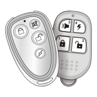
Provides instructions for replacing batteries in the 2-way and 1-way remotes.

Programming of codes for new transmitters

Programming of new transmitters

Details the step-by-step procedure for programming new remote transmitters into the system.

Programming 2-Way remote

Standard features

To ARM the system

Explains the procedure and system response for arming the vehicle security system.

Arm without siren chirp

Describes how to arm the system silently without audible siren chirps.

Defective Zone Bypass & Alert

Explains the system's response to active inputs during arming, including bypass notifications.

Passive arming

Automatically rearming

Details the feature where the system automatically re-arms if a door is not opened after disarming.

Alarm cycle

2nd step release start killer

Describes how to disable the starter kill feature after disarming the system.

Disarming without a transmitter

Disarming by using the PIN code

Provides instructions for disarming the system using a programmed PIN code.

Passive immobilizer

Dual stage shock sensor

Remote Zone1 sensor bypass

Details how to bypass the Zone 1 sensors using the remote control.

Remote Zone2 sensor bypass

Valet mode

Manage Engine start /running features

Safe status

Explains safety inputs required for proper engine operation and to prevent accidental damage.

Safety mode

Describes the safety mode that allows engine start only when the system is armed and no zones are triggered.

Safety mode for manual-type car

Details the procedure to set the system in Safety mode for manual transmission vehicles.

To remote start the vehicle

Fix time engine start

Temperature engine start

Clock time engine start

Arm with engine run mode

To perform Arm with engine run mode

Details the procedure for arming the vehicle while leaving the engine running.

Anti-Hi-Jack mode

Standby door switch activates

Explains the standby mode for Anti-Hi-Jack triggered by door activity.

Remote Anti-Hi-Jack

Describes how to activate the Anti-Hi-Jack mode remotely.

Ignition turn Anti-Hi-Jack

Details the feature where Anti-Hi-Jack mode activates upon ignition turn-on.

Door switch Anti-Hi-Jack

Explains Anti-Hi-Jack activation triggered by forced door opening and closing.

Turning off of the Anti-Hi-Jack mode

Additional service functions to control the system

Remote controlled additional channel (CH-1)

Controls for Channel 1, including trunk open, latched output, and timed output.

Program controlled additional channel (CH-2)

Controls for Channel 2, covering disarming output and timed/latched functions.

Program controlled additional channel (CH-3)

Program controlled additional channel (CH-5)

Additional channel (CH-6)

Changing of the PIN code to turn off the system

Entering the programming mode

System Installation

Mounting the Control Unit

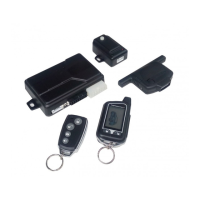
Guidelines for selecting an appropriate and secure location for the control unit.

Mounting the Shock Sensor

Recommendations for installing the shock sensor to ensure optimal detection and avoid false triggers.

WIRING DIAGRAM

20-PIN CON2 main connector wiring

6-PIN CON1 Connector for Engine start wiring

6-PIN CON1 Connector for Start/Stop button function

6-PIN CON3 Connector for Door Lock wiring

4-PIN Connector for sensors

CON1 engine start wire connection guide

CON2 wire connection guide

White/red Engine control input( tachometer orgenerator input)

Green/White (+) Foot brake input

Blue/White (-) Hand brake input

Red/black (-) Safety switch input (prog.)

6-PIN Connector for Central Door Locking Wiring

Related product manuals