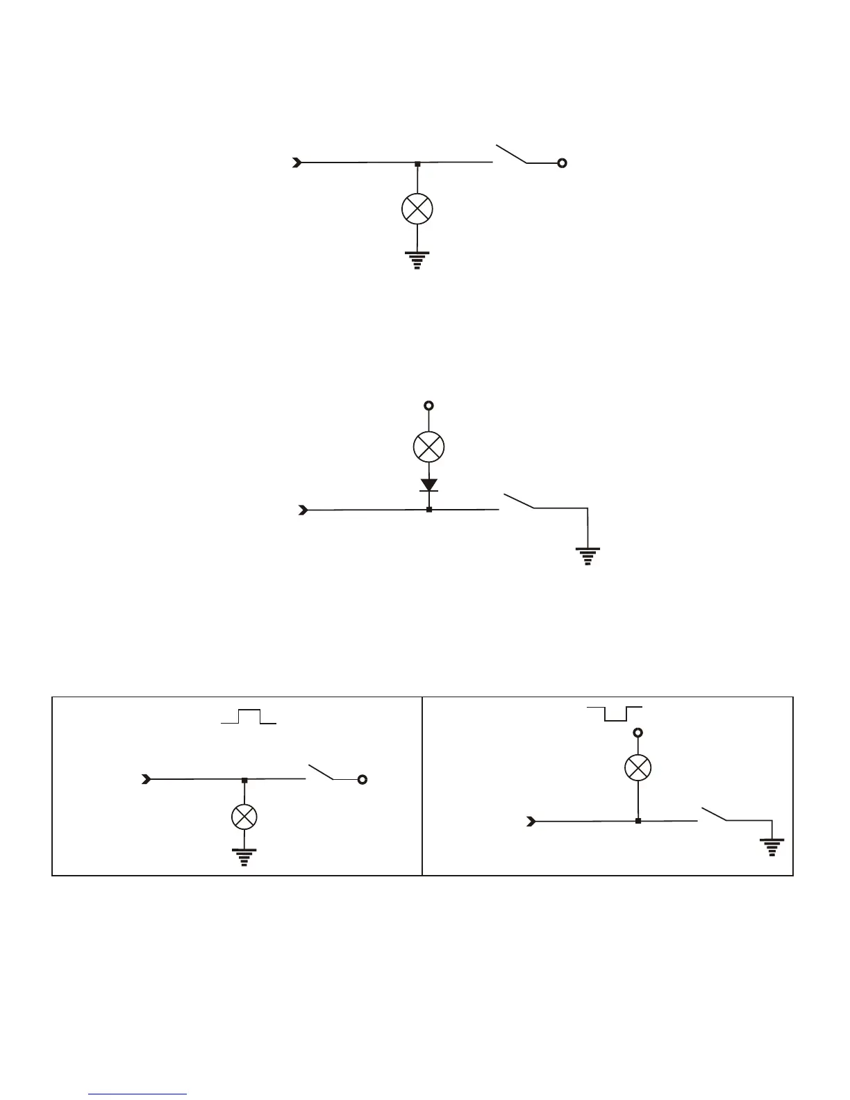
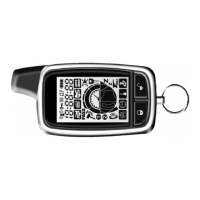
Red/black (-) Safety switch input (prog.)
Connect the wire to the PARK gear (-)switch in the vehicle. This wire will test with ground
with the gear selector in PARK position. This will prevent the vehicle from accidentally being
started while in a drive gear. This input must rest at ground in order for the remote start
system to operate. Connected properly the vehicle will only start while in PARK gear
position. This wire can be programmed (-) / (+) signal detect by table-3 of No.4.
Black (-) chassis ground connection
Remove any paint and connect this wire to bare metal, preferably with a factory bolt rather
than your own screw. (Screws tend to either strip or loosen with time.) We recommend
grounding all your components, including the siren, to the same point in the vehicle.
ORANGE (-) CH-5 ground-when-armed output (prog.)
This wire supplies a (-)500 mA ground as long as the system is armed (if programmed
armed output by (Table-2 of No.3). This output ceases as soon as the system is disarmed.
The orange wire may be wired to an optional starter kill relay.
Blue/White (-) Hand brake input
This wire MUST be connected to the vehicle's brake light wire. This is the wire that shows
(-) when the hand brake is ON. The remote start or turbo mode will be activate if the brake
Is ON position.
Green/White (+) Foot brake input
This wire MUST be connected to the vehicle's brake light wire. This is the wire that shows (+)
12V when the brake pedal is depressed. The remote start or turbo mode will be disabled or
shut down any time the brake pedal is depressed.
Green/white
Hand brake
Hand brake lamp
on dashboard
+12V
+12V
Green/white
Red/black
Red/black
Foot brake
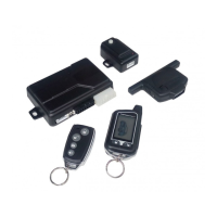
Park gear
Park gear
+ 12V
+ 12V
STOP lamps
Park gear lamp
Park gear lamp
(-) signal Safety sw
(+) signal Safety sw