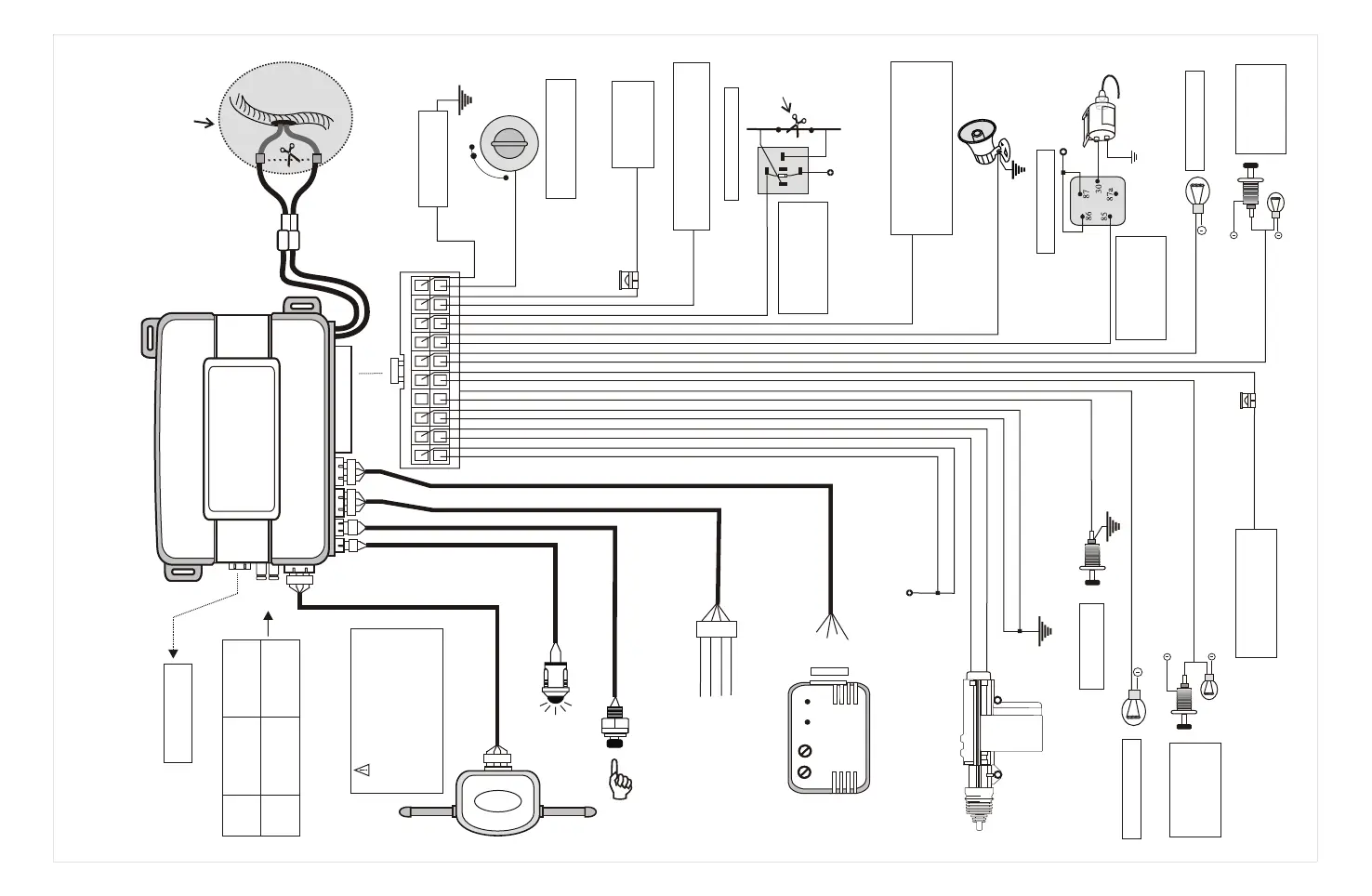
WIRING DIAGRAM :
J1
jumper
J2
jumper
Note: Disconnect the power from the main control unit
before setting the jumpers .
Antenna
Extend the whole wire, align it
with the intersection of dashboard
and the front window glass.
Keep it away from the metal at
least 5 centimeter to have the
best receiving condition.
2 stage shock sensor detector
External Ultra sonic &
micro-wave sensor port
+12VDC
- Ground
1st stage (-) trigger
2nd stage (-) trigger
R.F Antenna
With jumper Without jumper
Door lock / unlock
0.8sec.
for normal car.
Door switch arming
delay 0sec. for
normal car.
Door switch arming
delay 30sec. for
Dome light delay
car.
Door lock / unlock
4sec. for air
compressor car.
For optional Linking
module
Optional 30A
relay
CL-6700
CONTROL UNIT
1 2 3 4 5 6 7 8 9
10
11 12 13 14 15 16 17 18 19 20
Cutting the vehicle's
starter wire will leave
two sides- the ignition
switch side and the
starter solenoid side.
N/C BLOCKING
30
85
86
87a
87
Orange (-)
Orange / Black(-)
Connect to Red
from Siren
Brown(+)
Cut Existing
low current
Fuel pipe wire
Connect to +12Volt
ignition switch
40A relay
Programme Negative
Pulsed output for
2nd killer & Turbo feature
& Dome light
Black(-)
Connect to Chassis
Ground (-)
15Amp Fuse
Connect to (+)
12Volts Battery
Sources
Red (+)
Yellow(+)
Connect to Switched (+)
12Volts Ignition
O
C
N
C
A
S
F
T
F
O
Gray (-)
+12V
Trunk release
solenoid
Programme Negative
Pulsed output for
Trunk open & Turbo &
2nd stage unlock
Blue/red
Green/red
Blue
Green
Blue/black
Green/black
Door unlock-N/O
Door lock-N/O
Door unlock-Com
Door lock-Com
Door unlock-N/C
Door lock-N/C
Central door lock wiring
Door lock
Door unlock
Negative Pulsed when armed output
for Engine disable
Pink (-)
Programme Negative pulsed output
for the feature of:
1. Window close
2. Turbo
3. Horn pulse
White (+)
Connect to Hood
Pin Switch
Blue/white(-)
2-WAY ALARM
CONTROL UNIT
+12V
- Ground
(-) Ground
Green
Blue
Black
Red
Red
Black
Blue
Green
Status LED indicator
Valet/ Over-ride switch
J2
J1
Channel-2 (PROG.)
Channel-3(PROG.)
Channel-4 (PROG.)
For 2nd killer wiring
For trunk open wiring
White (+)
Right Parking Lights
Left Parking Lights
Connect to
Existing Positive
Door Pin Switch
(Ford Type)
Purple(+)
White/red (+)
Lights(+)or (-) input , for
the parking lights power
sources
10Amp Fuse
Green/white(-)
Connect to
Existing Negative
Door Pin Switch
(GM Type)
2-Stage
Shock Sensor
1
2
-14-