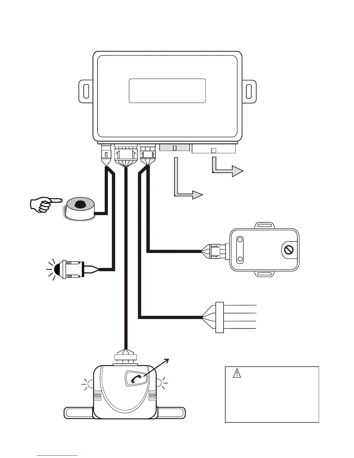
H2 12-PIN
CONNECTOR
Plug-in dual stage
shock sensor
R.F Antenna
Antenna
Extend the whole wire, align it
with the intersection of dashboard
and the front window glass.
Keep it away from the metal at
least 5 centimeter to have the
best receiving condition.
Blue LED
indicator
Blue LED
indicator
Call switch
WIRING DIAGRAM
Main control unit
H1 12-PIN
CONNECTOR
Valet switch
Plug-in dual color
LED indicator
Dual color LED
2 nd stage (-) trigger
1 st stage(-) trigger
- Ground
+12V DC output
Green
Blue
Black
Red
External Ultra sonic &
micro-wave sensor port
Dual-stage
Shock Sensor
H1
H2
Sensor
Tranciver
Valet/LED