-29-
+12V
Optional relay
1 2 3 4 5 6 7 8 9
10
11 12 13 14 15 16 17 18 19 20
(-) White/black
(-) Yellow/black
(-)Gray/black
(-) Gray
(-) Orange/black
(-) Brown/black
(-) Black/white
(+)Brown
(+) Yellow
(-) Pink
(-) negative pulsed when
disarmed output
Connect to Re
from Siren
Connect (+) 12V
Ignition switch
2 side Parking Lights
(+)White
(-) Blue
Connect to (-) Trunk Pin Switch
Connect to (-) Hood
Pin Switch
(+) /(-) White/red
Lights(+)or (-) input ,
for parking lights power
sources
10Amp Fuse
(+) Siren
Trunk release
solenoid
(-) negative pulsed output
for Window close (confort)
(-) pulsed output :
- 2nd stage unlock
- Remote latched
(-) pulsed output for :
-Dome light
-Keep engine run
-Turbo mode
(-) programme time
output 1~120sec.
(-) programme time
output 1~120sec.
CH-3
CH-4 (PROG)
CH-5 (PROG)
CH-6 (PROG)
CH-7 (PROG)
(-) Trunk
output
Immobilizer-2
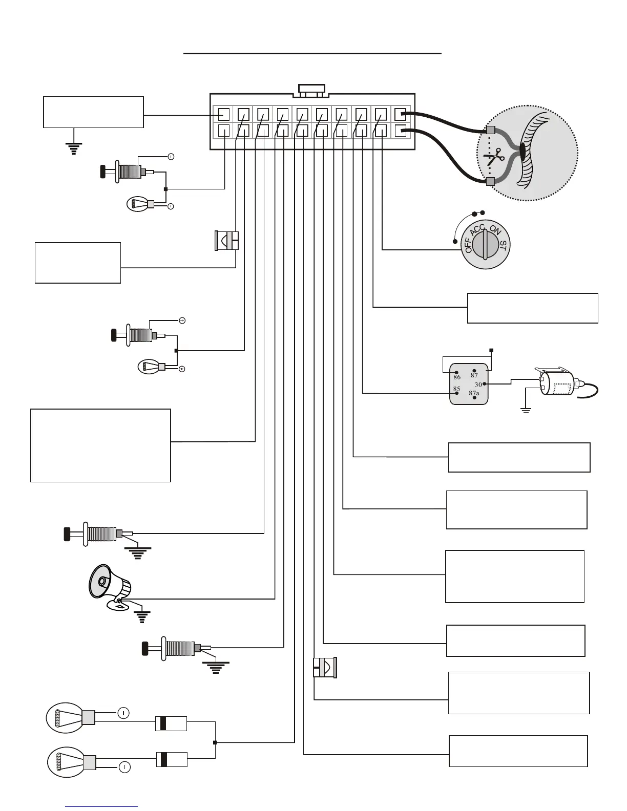
20 PIN MAIN PORT WIRING DIAGRAM
Cutting the vehicle's starter wire
will leave two sides- the ignition
switch side and the starter solenoid
side.
ENG / Starter
BLOCKING
6A2 diode
Connect to Chassis
Ground (-)
Black(-)
Connect to (-)
Negative Door
Pin Switch
(-) Green
Red (+)
Connect to (+)
12Volts Battery
Sources
15Amp
Fuse
(+) Purple
Connect to(+)
Positive Door
Pin Switch
(+) Red/black
Optional (+) input (PROG.)
- Reverse warning
- Head light warning
- Extra sensor input
(knock sensor)