12
1. Strip the individual wires by 12 mm. If the cable has
flexible conductors, it is recommended to use ferrules
on stranded wires. Use correct tools to press them.
2. Tighten the screw terminal with a torque of 5 Nm.
NOTICE! When connecting multiple backplates in
parallel, each screw terminal serves as a coupling point
for adjacent backplates. External junction boxes or flat
cables can be used if it is preferred.
NOTICE! It's recommended to follow the existing colour
codes used in the installation. Depending on national
standards, the colours of the cables can vary from the
illustrations. The illustrations in this manual follow the
IEC 60446 standard.
NOTICE! Protection against a broken PEN conductor
fault is only active when wired according to the TN-C-S
diagram.
NOTICE! Never connect Earth to both the PE and PEN
terminal.
NOTICE! Before turning on the power, make sure the
wires are properly connected and tightened. Test this by
pulling on each wire.
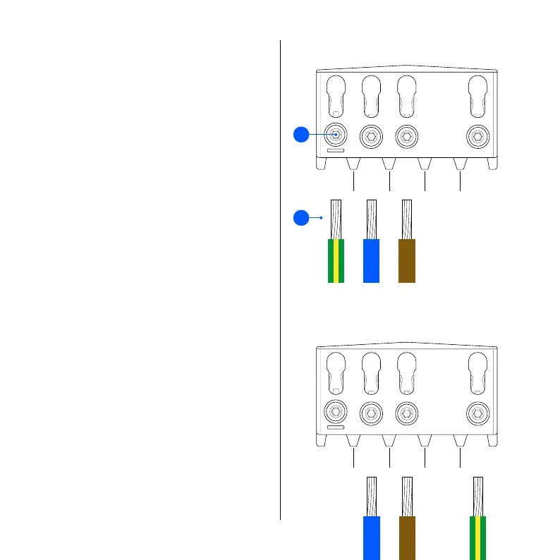
4
TT / TN-S network
PE N L1 –
TN-C-S network (PME)
– N L1 PEN
1
2
Backplate
Wiring