5
the arm if you get the symbols wrong. When you test the system and note an arm is
going the wrong way, just rotate the arm cable wires that are configured wrong and test
again until you get both arms opening on first power up of the board.
Wiring Single Gate: Connect arm cable to blocks labelled Mo1+, Mo1- on the control
board.
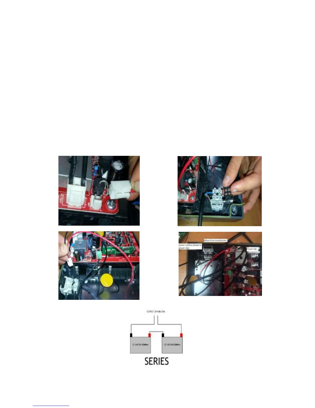
Powering your control board: The kit is supplied with a stand-alone transformer but
you can also buy this with the optional transformer built into the control box. Calculate
how much 2 core cable you will need to run out from the power source to the gate. It
should be a min of 1.5mm core diameter up to 50m and 2.5mm thereafter. Install the
stand-alone transformer near the 240v power source and lay the cable to the control
box. Connect the wires to the two existing transformer wires. Ensure that the 2 wires DO
NOT TOUCH*. Connect the wires on the other end into the control box grey 15 amp
fuse block (Separate unit just above the control board. Shown in image). Attach the 2
wires so they are connected as shown.