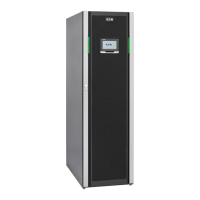
4 Eaton 93PM Emergency Lighting UPS (50 kW, 480V Three and Four-Wire UL 924) Installation and Operation Manual P-164000569—Rev 03
After initial startup, the battery run time on the front panel display indicates two minutes. After the 24-hour float
charging period and automated battery testing, the actual battery run time is determined and the actual battery
run time is displayed.
After the float period is completed, the charger is disconnected and the batteries are allowed to rest for up to
672 hours (28 days) maximum rest time. If the battery voltage falls below the opportunity charge level of 2.1V/
cell during the first 240 hours (10 days) of the rest period, an alarm sounds.
An ABM charge cycle is initiated whenever one of these four conditions occurs since the last charge cycle:
• The batteries have rested over the maximum rest time of 672 hours.
• Accumulated discharge time is over a maximum battery discharge time of 20 seconds.
• Battery voltage is under the opportunity charge level of 2.1 volts/cell and the cabinet has been in rest mode
for longer than 240 hours.
• A Battery Test command has been initiated.
11..11..77 EEmmeerrggeennccyy PPoowweerr OOffff
WARNING
• Emergency Power Off (EPO) and Remote Emergency Power Off (REPO) functionality has been disabled
for UL 924 emergency lighting systems. To remove power from the system a LOAD OFF command (see
paragraph 7.3.12 Using the UPS LOAD OFF Command) must be given using the front panel controls and all
breakers opened.
• Power is present inside the UPS cabinet until the upstream input feeder circuit breakers and battery
breakers are opened.
11..22 OOppttiioonnss aanndd AAcccceessssoorriieess
Contact an Eaton sales representative for information about the following options.
11..22..11 IInntteeggrraatteedd BBaatttteerryy CCaabbiinneett
Battery backup protection with additional runtime can be provided by equipping the UPS system with up to four
Integrated Battery Cabinets (IBCs) containing sealed lead-acid, maintenance-free batteries. The IBCs are
housed in single, free-standing cabinets designed for line-up-and-match installation, but may be installed
separate from the UPS cabinet. An external battery disconnect switch or tie point must be used when three or
four IBCs are located separate from the UPS cabinet. The IBCs may be installed on either the right or left side
of the UPS cabinet. The recommended installation location for adjacent battery cabinets is on the right side of
the UPS cabinet.
11..22..22 SSiiddeeccaarr IInntteeggrraatteedd AAcccceessssoorryy CCaabbiinneett--BByyppaassss
A Sidecar Integrated Accessory Cabinet-Bypass (SIAC-B) provides maintenance bypass functions. The SIAC-B
is available in two, three, or four breaker configurations enabling power to completely bypass the UPS. The
UPS can then be safely serviced or replaced without interrupting power to critical systems. The four breaker
configuration provides a convenient method for removing power from the UPS when using the maintenance
bypass to supply the load. The SIAC-B is housed in a cabinet attached to the UPS cabinet. The SIAC-B may be
installed on either the right or left side of the UPS cabinet. The SIAC-B can also be used for top entry wiring
access.
Introduction

 Loading...