2
Instructions and Operation P52899
Effective July 2019
Box 1 and Box 2 non-combination enclosed
control and C600M cover control kit wiring
EATON www.eaton.com
General information
This publication is to be used for Eaton non-combination enclosures
designed to accept the M22 series 22 mm cover control devices.
If the enclosure catalog number already has cover control devices
mounted, the existing reverse “c” shape bracket can be reused.
If the enclosure catalog number includes a blank rectangular cover,
remove it prior to installing the cover control kit (see instructions
below).
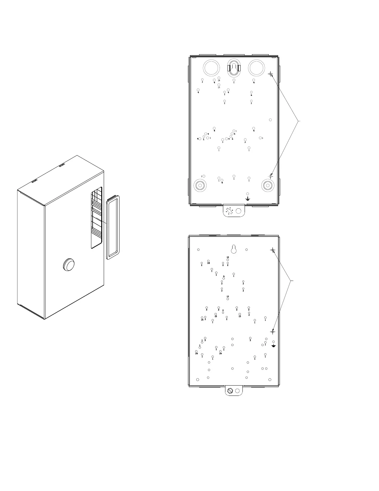
Cover control installation
1. Remove rectangular blank cover by pushing on the blank cover
from the back side.
2. Discard blank cover.
3. Using the included mounting screws, mount the C600M cover
control to the base of the enclosure in the holes designated by
the arrows below.
4. Terminate the wires from the M22 operators onto the starter/
contactor as illustrated in “C600M Kit Wiring Instructions“
(seepage 4).
Box 1 enclosure
COVER CONTROL
MOUNTING LOCATION
Box 2 enclosure
COVER CONTROL
MOUNTING LOCATION