2
Instruction Leaflet IL 29C401J
Effective December 2010
Installation Instructions for Series C F-Frame
Motor Circuit Protector Type HMCP & HMCPS
EATON CORPORATION www.eaton.com
DO NOT ATTEMPT TO INSTALL OR PERFORM MAIN-
TENANCE ON EQUIPMENT WHILE IT IS ENERGIZED.
DEATH, SEVERE PERSONAL INJURY, OR SUBSTAN-
TIAL PROPERTY DAMAGE CAN RESULT FROM
CONTACT WITH ENERGIZED EQUIPMENT. ALWAYS
VERIFY THAT NO VOLTAGE IS PRESENT BEFORE
PROCEEDING WITH THE TASK, AND ALWAYS FOLLOW
GENERALLY ACCEPTED SAFETY PROCEDURES.
EATON IS NOT LIABLE FOR THE MISAPPLICATION OR
MISINSTALLATION OF ITS PRODUCTS.
1. INTRODUCTION
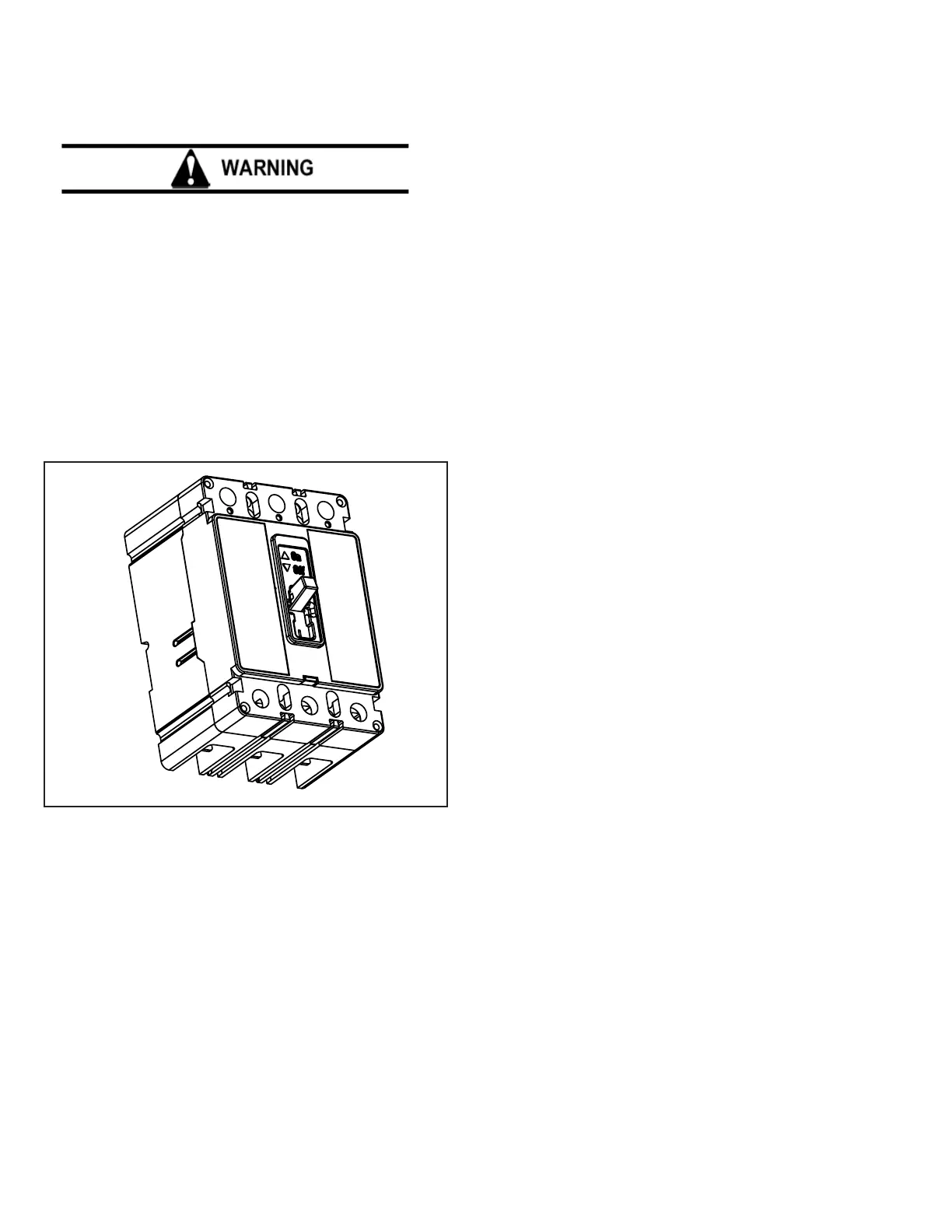
Fig. 1-1 F-Frame Series C Motor Circuit Protector
The user is cautioned to observe all recommendations, warnings,
and cautions relating to the safety of personnel and equipment as
well as all general and local health and safety laws, codes, and
procedures.
The recommendations and information contained herein are
based on Eaton experience and judgement, but should not be
considered to be all-inclusive or covering every application or
circumstance which may arise. If any questions arise, contact
Eaton for further information or instructions.
General Information
The F-Frame Series C instantaneous-only (magnetic) motor
circuit protector (MCP) (Fig. 1-1) is available in ratings from
3A to 150A continuous current for motor starter sizes 0 through
4. Designated as the Type HMCP and HMCPS, it is available
in 3-pole frames only. The MCP is designed to comply with the
applicable requirements of Underwriters Laboratories, Inc. Stan-
dard UL489 and the International Electrotechnical Commission
Recommendations No. IEC 947.
The MCP is a UL recognized component under le E7819. It
is used primarily to provide short-circuit protection as part of a
combination controller where other circuit protective functions
are performed by other devices within the controller. The MCP
is not suitable for reverse feed applications.
This instruction leaet (IL) gives procedures for installation,
operation, inspection, and checking of F-Frame MCP’s by the
end user.
Conforming to N.E.C. requirements, the maximum HMCP and
HMCPS trip ampere value is set by the motor FLA. Since there
are various types and classes of motor designs (based on duty
cycle, electrical load, and manufacturer’s discretion), locked
rotor currents (and resulting in rush current magnitudes) vary.
These are normally identied by N.E.C. codes. The listed
HMCP and HMCPS trip ampere value is considered typical, but
not all inclusive. This is the reason for the adjustable magnetic
trip setting, which compensates for different actual motor in
rush currents. Trip level adjustments are normal and sometimes
necessary to enable the motor to start without nuisance tripping
especially when motor or system conditions induce higher than
expected in rush currents. These circumstances may be beyond
the control of the HMCP and HMCPS, relative to its allowable
trip setting. Such conditions should be treated as a special case
which may be referred to Eaton.
 Loading...