4
Instruction Leaflet IL 29C401J
Effective December 2010
Installation Instructions for Series C F-Frame
Motor Circuit Protector Type HMCP & HMCPS
EATON CORPORATION www.eaton.com
Table 2-1. TERMINAL TYPES
Terminal Catalog
Number
Terminal
Body
Material
Screw
Head
Type
AWG
Wire
Range
Metric
Wire
Range
Wire
Type
Torque
Value LB in.
(N•m)
3TA225FD(1) Alumi-
num
3/16
Socket
Hex
#4-4/0 25-95 Cu/Al 120 (13.6)
3TA225FDM(1) Alumi-
num
5mm
Socket
Hex
#4-4/0 25-95 Cu/Al 120 (13.6)
3TA225FDK(1)
(2)
Alumi-
num
5/16
Socket
Hex
#6-300 16-150 Cu/Al 275 (31)
3TA100FD(1) Alumi-
num
Slotted #14-1/0 2.5-50 Cu/Al See Table
2-2
3TA50FB(1) Alumi-
num
Slotted #14-#4 2.5-16 Cu/Al See Table
2-2
3T100FB(1) Steel Slotted #14-1/0 2.5-50 Cu/Al See Table
2-2
3T150FB(1) Stainless
Steel
Slotted #4-4/0 25-95 Cu
Only
See Table
2-2
Note: Terminal wire connectors are UL listed for standard wire sizes as dened
in UL 486A and UL 486B.
(1) Package of three
(2) Individual terminal identied as TA225FD1
TABLE 2-2. TERMINAL TORQUE VALUES FOR SLOTTED HEAD
Metric Wire
Range
Torque Value.
N•m
AWG Wire
Range
Torque Value
Lb. In.
2.5-6 3.96 #14-#10 35
10 4.52 #8 40
16-25 5.09 #6-#4 45
35-95 5.65 #3-4/0 50
TABLE 2-3. BOLTED CONNECTIONS (KEEPER NUT OR END CAP)
Termination Cata-
log Number
Screw Head
Type
Nut Thread
Size
Torque Value.
Lb. In. (N•m)
KPR1A / KPR1AM User Supplied 10-32 / M5 35(4.0)
KPEKxxx Slotted 10-32 / M5 35(4.0)
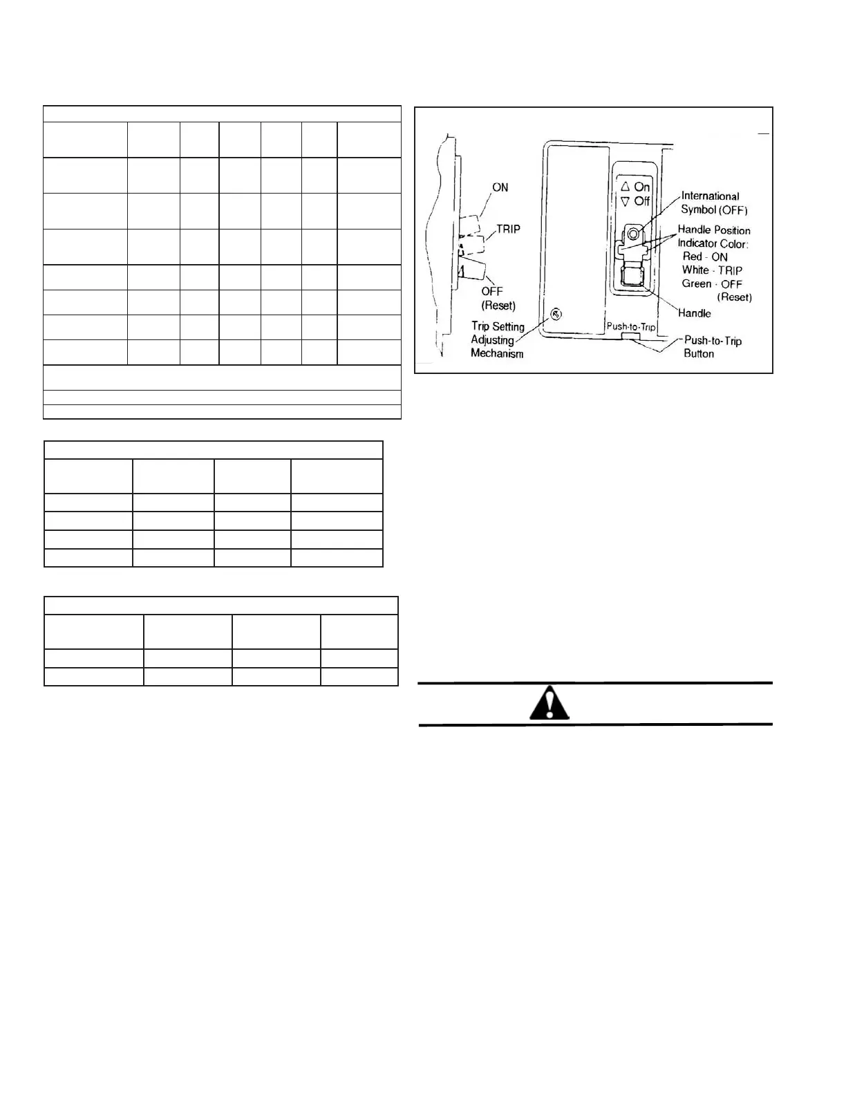
3. MANUAL OPERATION
The MCP is normally operated by the handle or the PUSH-TO-
TRIP button. The MCP handle has three indicating positions,
two of which are shown on the cover by raised lettering to indi-
cate ON and OFF. On the sliding handle barrier, ON, OFF, and
TRIP are also shown by a color-coded strip for each MCP handle
position: red for ON, white for TRIPPED, and green for OFF.
On the sliding handle barrier, ON/OFF is also indicated by the
international symbols I/O. (See Fig. 3-1).
CIRCUIT BREAKER RESET
After tripping, the MCP is reset by moving the MCP handle to
the extreme OFF position.
PUSH-TO-TRIP Button
The PUSH-TO-TRIP button checks the tripping function and is
used to periodically exercise the operating mechanism. The but-
ton is designed to be operated by using a small screwdriver.
Fig. 3-1 Frame MCP Manual Controls
Adjustment of Trip Setting
The trip setting adjusting mechanism permits the MCP trip range
to be changed. The mechanism consists of a cam with eight
positions for different trip levels. The trip levels are labeled A
through H. Trip values are shown on the MCP cover nameplate
and in Tables 3.1 and 3.2. To adjust the trip level, perform the
following steps:
3-1. Determine the motor locked rotor current from
the motor nameplate. Refer to Table 3-1 and
select appropriate MCP trip setting. Depress
and rotate adjustment button clockwise to the
setting.
CAUTION
A ROTATION STOP PREVENTS THE ADJUSTMENT
BUTTON FROM BEING ROTATED COUNTER-CLOCK-
WISE BEYOND POSITION A. THE MCP CAN BE DAM-
AGED IF THE BUTTON IS FORCED PAST A IN THE
COUNTER CLOCKWISE DIRECTION.
3-2. For closest protection, turn the adjustment but-
ton counter-clockwise to successively lower
settings until the MCP trips when the the motor is started. When
this setting has been determined, turn the adjustment button
clockwise to the next highest setting. The MCP is now adjusted
for normal operation.
3-3. If the MCP does not trip at the lowest setting (A), leave
the adjustment button at this position.
 Loading...