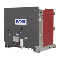
Do you have a question about the Eaton Ulusoy URING36 C - SF6 and is the answer not in the manual?
Details various components like breaker locks, buttons, indicators, and housings.
Provides dimensions for low voltage cutter, cabin, mechanism, and terminals.
Ensures cells are free of foreign objects and covers are correctly placed before powering.
Procedures for testing phase conformity using voltage indicators and cable tests.
Details mimic panel elements like safety locks, indicators, and operation buttons.
Identifies components on the protection and control board like relays and indicators.
Steps for powering the switchgear, including disconnector and spring assembly operations.
Procedure to turn the disconnector off and subsequent status checks.
Steps for locking buttons and turning the breaker off.
Procedures for turning the breaker on and managing safety locks.
Instructions for turning the disconnector and earthing disconnector on and off.
Details electrical terminal connections for auxiliary supply and signals.
Procedure to replace a faulty voltage indicator on the low voltage board.
Troubleshooting steps for voltage indicator lights and cell front cover operation.
Guides to resolve issues with earthing disconnector, disconnector, and breaker functions.
Troubleshooting steps for the breaker spring assembly engine, including power supply checks.
| Rated Voltage | 36 kV |
|---|---|
| Insulation Medium | SF6 |
| Rated Frequency | 50/60 Hz |
| Mechanical Endurance | 10000 operations |
| Rated Current | 1250 A |
| Rated Short-Circuit Breaking Current | 25 kA |
| Rated Peak Withstand Current | 63 kA |


