3
Instruction Leaflet IL 29C401J
Effective December 2010
Installation Instructions for Series C F-Frame
Motor Circuit Protector Type HMCP & HMCPS
EATON CORPORATION www.eaton.com
2. INSTALLATION
The installation procedure consists of inspecting and
mounting the MCP, connecting and torquing the line and
load terminations, and attaching terminal shields or barri-
ers, when required. To install the MCP, perform the follow-
ing steps:
F-Frame MCPs are factory sealed. UL489 requires that
internal accessories be installed at the factory. Where
local codes and standards permit and UL component
recognition is not required, internal accessories can
be eld installed. Accessory installation should be
done before the MCP is mounted and connected. The
MCP has a cover interlock which requires the handle
to be in the OFF positon when removing or installing
the cover.
If the HMCP or HMCPS is opened at locations other than
authorized, the side located adhesive seal must be re-
moved and the ‘UR’ nameplate mark must be covered.
Both of the above steps are required to comply with UL
requirements.
No internal maintenance, adjustments, or replacement
items are authorized. Misuse, mishandling, or unauthor-
ized adjustments can change the operating characteristics
of the HMCP or HMCPS.
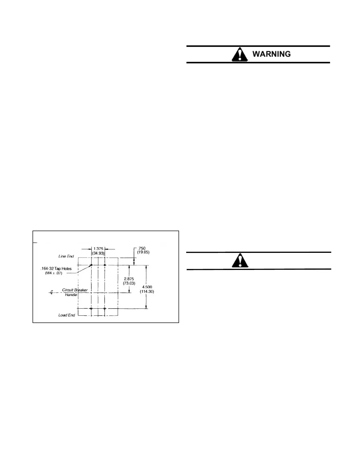
Fig. 2-1 MCP, HMCP and HMCPS Mounting Bolt Drilling Plans
Mounting hardware and unmounted accessories (where required)
are supplied in separate packages.
2-1. Make sure that the MCP is suitable for the intended instal-
lation by comparing nameplate data with system requirements.
Inspect the MCP for completeness and damage before mounting.
BEFORE MOUNTING THE MCP IN AN ELECTRICAL
SYSTEM, MAKE SURE THE MCP IS SWITCHED TO THE
OFF POSITION AND THAT THERE IS NO VOLTAGE
PRESENT WHERE WORK IS TO BE PERFORMED. THE
VOLTAGES IN ENERGIZED EQUIPMENT CAN CAUSE
DEATH OR SEVERE PERSONAL INJURY.
2-2. To mount the MCP, perform the following steps:
Note: If terminal shield or interphase barriers are to be
installed on the MCP, install them after the terminals
are connected.
a. For individual mounting panels, make sure that
mounting panel is predrilled using drilling plan
(Fig. 2-1).
b. If MCP includes factory installed internal ac-
cessories, make sure accessory wiring can be
reached when the MCP is mounted.
c. Position MCP on mounting surface.
d. Install mounting screws, washers, and nuts.
Tightenscrewsrmly,butdonotexceed28
pound-inches (3.16 N.m)
2-3 If an optional terminal end cover is to be in
stalled with the MCP (usually line end
only), it must be positioned before cable is
connected to terminals.
CAUTION
WHEN ALUMINUM CONDUCTORS ARE USED, THE
APPLICATION OF A SUITABLE JOINT COMPOUND IS
RECOMMENDED TO REDUCE THE POSSIBILITY OF
TERMINAL OVERHEATING. TERMINAL OVERHEATING
CAN CAUSE DAMAGE TO THE MCP.
2-4. After mounting the MCP, line and load cables and
accessory leads should be connected. (See ac
cessory schematic diagram on side of MCP.)
2-5 If required, install terminal shield on MCP cover
with mounting screws provided.
2-6 If required, install interphase barriers by sliding bar-
riers into dovetail grooves between terminals.
2-7 After the MCP is installed, check all mounting hard-
ware and terminal connecting hardware for correct
torque loading. Torque values for lineload termi-
nals are given in Tables 2-1 and 2-2 and on
the MCP nameplate.
 Loading...