EasyManua.ls Logo

Eaton Cutler-Hammer Digitrip RMS 310 User Manual

Eaton Cutler-Hammer Digitrip RMS 310
14 pages
To Next Page IconTo Next Page
Page #1 background imageLoading...
Page #1 background image
Instructions for the Digitrip RMS 310 3
-
Pole and 4
-
Pole Trip Unit Installation
and Operation with L
-
Frame and MDL
-
Frame Series C Circuit Breakers
Table
of
Contents
Description Page
1
.O
General Information
...............................................
1
1.1
Protection
..............................................................
1
2.0
UL Listed Devices
..................................................
2
3.0
Installation
.............................................................
2
3.1
Preparation (All Trip Units)
.....................................
2
3.2
4
-
Pole Trip Unit Installation
.....................................
2
3.3
Ground Fault Trip Unit Installation
..........................
3
3.3.1
General
..................................................................
3
3.3.2
Installation
.............................................................
3
3.4
3.5
4.0
4.1
4.2
4.3
4.4
5.0
5.1
5.2
5.3
5.4
5.5
5.6
6.0
6.1
6.2
3
-
Pole (Non
-
Ground Fault) Trip Unit Installation
.....
5
Final Installation Instructions (All Trip Units)
...........
6
Principle of Operation
............................................
6
General
..................................................................
7
Overload Trip
.........................................................
7
Short Delay/lnstantaneous Trip
..............................
7
Ground Fault Protection
.........................................
7
Protection Settings
.................................................
7
General
..................................................................
7
Short Delay Pick
-
up Settings
.................................
7
Short Delay Time Settings
.....................................
7
Instantaneous Pickup Setting
................................
7
Ground Fault Pick
-
up Setting
.................................
7
Ground Fault Time Settings
...................................
8
Testing
...................................................................
8
Functional Field Testing
.........................................
8
Performance Testing for Ground Fault Trip Units
....
8
-
6.2.1
Code Requirements
...............................................
8
6.2.2
Standards Requirements
.......................................
9
6.2.3
General Test Instructions
.......................................
9
7.0
Rating Plug
..........................................................
12
8.0
References
..........................................................
12
8.1
Series C L
-
Frame Molded Case
Circuit Breakers
...................................................
12
8.2
Internal Accessories
............................................
12
PRESENT BEFORE PROCEEDING WITHTHETASK,
AND ALWAYS FOLLOW GENERALLY ACCEPTED
SAFETY PROCEDURES.
MISAPPLICATION
OR MISINSTALLATION
OF ITS
PRODUCTS.
CUTLER
-
HAMMER
IS
NOT LIABLE FORTHE
The user is cautioned to observe all recommendations,
warnings, and cautions relating to the safety of personnel
and equipment as well as all general and local health and
safety laws, codes, and procedures.
The recommendations and information contained herein
are based on Cutler
-
Hammer experience and judgement,
but should not be considered to be all
-
inclusive or cover
-
ing every application or circumstance which may arise. If
any questions arise, contact Cutler
-
Hammer for further
information or instructions.
Fig.
1
Digitrip RMS 310
Trip
Unit
for
3
-
Pole L
-
Frame
&
MDL Frame Series C Circuit Breaker
1
.O
GENERAL INFORMATION
A
A
WARNING
DEATH, SEVERE PERSONAL INJURY,
OR
SUBSTANTIAL PROPERTY DAMAGE CAN RESULT
FROM CONTACT WITH ENERGIZED EQUIPMENT. DO
NOT ATTEMPT INSTALL
OR
PERFORM
MAINTENANCE ON EQUIPMENT WHILE IT
IS
ENERGIZED. ALWAYS VERIFY THAT NO VOLTAGE
IS
1.1
Protection
The Digitrip RMS
31
0,
illustrated in Figure
1,
is an elec
-
tronic trip unit that incorporates a microprocessor
-
based
custom application specific integrated circuit design for
use with Series C L
-
Frame and MDL Frame Molded Case
Circuit Breakers.
The Digitrip RMS
310
provides true RMS current sensing
for proper correlation with thermal characteristics of
conductors and equipment. Interchangeable rating plugs
Effective
March 2003
Supersedes I.L. 29C615D dated
July 1998
EATON
I.L. 29C615E
Courtesy of NationalSwitchgear.com
Question and Answer IconNeed help?

Do you have a question about the Eaton Cutler-Hammer Digitrip RMS 310 and is the answer not in the manual?

Eaton Cutler-Hammer Digitrip RMS 310 Specifications

General IconGeneral
ManufacturerEaton Cutler-Hammer
Voltage Rating600V AC
Current Rating15A to 250A
Protection FeaturesOverload, Short Circuit, Ground Fault
Amperes15A to 250A
StandardsUL, CSA, IEC (Consult specific breaker documentation)

Summary

General Information

Protection Features

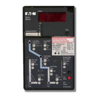
Describes the Digitrip RMS 310 electronic trip unit, its microprocessor design, and RMS current sensing.

UL Listed Devices

Installation Procedures

Trip Unit Preparation

Covers inspecting the trip unit for suitability, completeness, and damage before installation.

4-Pole Trip Unit Installation

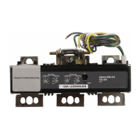
Details steps for installing a 4-pole trip unit and its current sensor, including connector alignment.

3-Pole Ground Fault Trip Unit Installation

Explains installing ground fault trip units, including neutral sensor and alarm relay connections.

3-Pole Non-Ground Fault Trip Unit Installation

Outlines installing 3-pole non-ground fault trip units and securing them with correct torque.

Final Installation Steps

Covers installing accessories, barriers, covers, and ensuring correct rating plug installation.

Principle of Operation

Trip Unit Operation Overview

Explains how the integrated circuit and microcomputer process sensor data for protection functions.

Overload Trip Mechanism

Details the trip unit's response to overload currents, including trip times and thermal memory effect.

Short Delay and Instantaneous Trip Function

Describes the operation of short delay and instantaneous trip functions based on current levels and time delays.

Ground Fault Detection

Explains how ground fault currents are detected using residual sensing and the relevant settings.

Protection Settings

General Settings and Status Light

Covers setting trip unit parameters, the role of the rating plug, and interpreting the status light.

Short Delay Settings

Details available adjustments for short delay pick-up and time delay (I2t ramp or flat response).

Instantaneous Pickup Setting

Explains setting the instantaneous pickup, often linked to the short delay time setting.

Ground Fault Settings

Describes the settings for ground fault pick-up and time delay for selective coordination.

Testing Procedures

Functional Field Testing

Explains performing functional testing using the STK2 Test Kit and the trip unit's test receptacle.

Ground Fault Performance Testing

Covers NEC requirements, UL standards, and general test instructions for ground fault protection systems.

Rating Plug

References and Accessories

Related Instruction Leaflets

Lists instruction leaflets for L-Frame breakers and time-current curves for reference.

Internal Accessories

Lists optional internal accessories that mount on the trip unit and their corresponding instruction leaflets.

Related product manuals