I.B. ATS-CP01
Page vi
Effective 5/98
LIST OF FIGURES
Figure Title Page
1-1 Typical Load Transfer Switch (circuit breaker type) Schematic.................................................................2
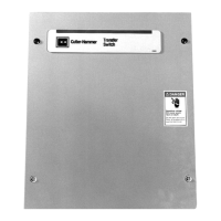
1-2 Typical Mini Transfer Switch with Dead Front Attached ............................................................................3
1-3 Typical Mini Transfer Switch with Dead Front Removed...........................................................................3
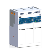
3-1 Typical Power Panel..................................................................................................................................6
3-2 Insulated Case Switch...............................................................................................................................6
3-3 Insulated Case Circuit Breaker..................................................................................................................7
3-4 Side View and Rear View of Power Panel (terminal connections for
SPB 800-1200 AMP) .................................................................................................................................7
3-5 Voltage Selection Panel.............................................................................................................................8
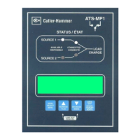
3-6 IQ Transfer.................................................................................................................................................8
3-7 Neutral Connection....................................................................................................................................9
3-8 Charger Mounting Dimensions in Inches (mm) .......................................................................................10
3-9 Typical Mini Switch Enclosure.................................................................................................................10
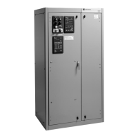
4-1 Enclosed Fixed Mount Transfer Switch, 600-4000 amperes...................................................................13
4-2 Enclosed Fixed Mount Transfer Switch, 600-1200 ampere without Option 17C.....................................14
4-3 Side View and Rear View of Power Panel (terminal connections for
SPB 800-1200 AMP) ...............................................................................................................................16
4-4 Seismic Tested and Approved Product Mounting Instructions................................................................17
5-1 Pumping Handle Charges Stored Energy Mechanism............................................................................18
5-2 Switching Device Closing Precautions ....................................................................................................19
LIST OF TABLES
Table Title Page
1.1 Withstand Ratings......................................................................................................................................3
1.2 Transfer Switch Catalog Number Explanation...........................................................................................4
3.1 Transfer Switch Equipment Enclosures...................................................................................................11
4.1 Wire Size for Power Cable Connections..................................................................................................16
7.1 Periodic Maintenance Procedures...........................................................................................................23

 Loading...